In a perfect world, every maintenance man stagehand and security guard does not carry a 5 W radio. Every car driving by doesn't have a 1000 W CB radio. BUT in my world such RF emitters exist. R29 & C16 are an external RF trap. Also should be included and not shown, 11 turns fat wire around a 1 cm coil form between speaker jack and amp output, parallel a 10 ohm 3 watt resistor. These are left out of most lab designs on here, and included in most successful commercial amps. Keep these components away from the high impedance feedback path and the input, IMHO. In my AX6/(ST120 djoffemod) build, the zobel r29 & c16 are outside the 11 turn inductor, mounted on the back of the dual banana jack for speakers in fact.R29 C16 should not be necessary, but you can include them on the PCB and leave them empty.
C3 the 150 pf parallel the input may be a bit heavy handed. I had to go up from 0 to 68 pf parallel the input jack on my AX6 to get rid of an AM radio station. Sports talk radio, particularly vile.
These RF traps are only fully effective in a steel or steel mesh case.
Last edited:
OLF2 majorR2
Dear LV,
Made all modifications as suggested. Kept all options available in the scheme. If any thing is to be included further, please suggest.
.dip file is included with extra .asc extension. just remove the asc extension to open the file. Hope it gets uploaded.
--gannaji.
Dear LV,
Made all modifications as suggested. Kept all options available in the scheme. If any thing is to be included further, please suggest.
.dip file is included with extra .asc extension. just remove the asc extension to open the file. Hope it gets uploaded.
--gannaji.
Attachments
Why didn´t you say so when you posted it? 🙄It is a .rar file. DIY does not accept rar files. I changed the extension to zip. Please change it back to rar and it should open.
WinZip got crazy trying to open it.
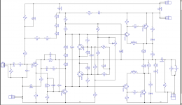
R29 and C16's primary role would be as a Zobel, not a RF trap: their purpose is to keep the output terminated by a low impedance at high frequencies, to prevent the loop gain of the amplifier from wandering into hazardous regions.R29 & C16 are an external RF trap. Also should be included and not shown, 11 turns fat wire around a 1 cm coil form between speaker jack and amp output, parallel a 10 ohm 3 watt resistor.
As a side effect, it will also attenuate and dissipate some of the HF ingress, but that is not the reason why it is included in 99% of the amplifiers.
(If you need it, I can show you an example of a real RF filter)
Here, this network is split between C15/R28 and C14/R27: together they form the equivalent of a 44nF/4.1ohm Zobel network, but they also stabilize the CFP OPs.
An inductive Zobel can be useful, for capacitive loads (relatively rare) or relatively long cables behaving capacitively at some frequencies.
R18 still needs to be changed to 100K. If any thing is to be included further, please suggest.
Sorry Dear Fahey !
My winrar program opens almost any compressed file. After renaming also, this file opened normally in my computer.
The latest way I used in post #23 is best.
My winrar program opens almost any compressed file. After renaming also, this file opened normally in my computer.
The latest way I used in post #23 is best.
I took it as given you had managed the high freq loop gain of the base circuit already. When dynaco post ST120 shipment suggested 1000 ohms series .047 uf on the back of the speaker jack OUTSIDE the 11 turn inductor , it pretty obviously had something to do with the outside world. Like more portable FM transmitters in 1970 than in 1966. And warrenty calls. Other thousands of "zobels" may have to do with internal stability as you say.R29 and C16's primary role would be as a Zobel, not a RF trap: their purpose is to keep the output terminated by a low impedance at high frequencies, to prevent the loop gain of the amplifier from wandering into hazardous regions.
As a side effect, it will also attenuate and dissipate some of the HF ingress, but that is not the reason why it is included in 99% of the amplifiers.
(If you need it, I can show you an example of a real RF filter)
Here, this network is split between C15/R28 and C14/R27: together they form the equivalent of a 44nF/4.1ohm Zobel network, but they also stabilize the CFP OPs.
An inductive Zobel can be useful, for capacitive loads (relatively rare) or relatively long cables behaving capacitively at some frequencies.
Scored a full parts kit including exotic leaded BAT48 & HTE5L100 (schottky 5A 100 v). 44 v 2 A transformer for 50 v rail. Rains of October due in 2 weeks. Build of OldFashMax to follow.
Why didn´t you say so when you posted it? 🙄 WinZip got crazy trying to open it.
That's just dumb of WinZip.
I wrote a whole explanation of how easy it could know/suspect it wasn't a ZIP, but my computer ate it.
File format - Wikipedia
Here's the picture.
Attachments
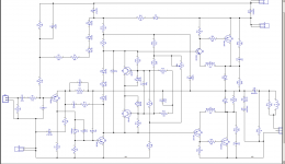
I took an 1980's Maplin 225WRMS amp and brought it up to date.
I just used two output transistors to bring it down to a 100watts.
I added CCS to LTP.
I used all modern bi polar transistors.
I added better decoupling to power rails.
I also decoupled front end from outputs with RC.
This version also has DC servo.

I just used two output transistors to bring it down to a 100watts.
I added CCS to LTP.
I used all modern bi polar transistors.
I added better decoupling to power rails.
I also decoupled front end from outputs with RC.
This version also has DC servo.
Last edited:
Thank you dear Nigel ! Is that amp single supply with cap out ?
Its a dual rail amplifier running off +/-40 volts dc so no output capacitor.
Dear elvee,
Please find the R3 files. The png, Diptrace and Eagle format files with .asc added to enable uploading. Please remove the ase extension and the files can be opened in Diptrace and Eagle.
Any PCB gurus to help please ?
--gannaji
Please find the R3 files. The png, Diptrace and Eagle format files with .asc added to enable uploading. Please remove the ase extension and the files can be opened in Diptrace and Eagle.
Any PCB gurus to help please ?
--gannaji
Attachments
The electrical schematic looks fine.
Can you post a screenshot of the PCB layout (if it is included in the files)?
Can you post a screenshot of the PCB layout (if it is included in the files)?
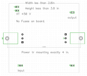
This is the final PCB shape I would prefer depending on the Heat-sinks I have.
The height not more than 3.8 inches to fit in 4in height heatsinks and box. Distance between power BJT mounting holes to be 4 in . The actual pcb width can be more or less as suits the design, but not more than 8 inches. Thanks for any help.
The height not more than 3.8 inches to fit in 4in height heatsinks and box. Distance between power BJT mounting holes to be 4 in . The actual pcb width can be more or less as suits the design, but not more than 8 inches. Thanks for any help.
Attachments
Dear all,
I do not know why, there is some problem in the Diptrace file posted. I made many changes, compared to the png file posted, and reposted as R4. Please remove the asc extension and it can be opened in Diptrace.
The eagle file posted is exported from diptrace file.
The png file, R3 is unchanged.
--gannaji
Attachments
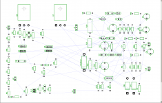
Difficult to tell without seeing the finished result, but it doesn't look promising.Dear Elvee,
I started in my own way to start the lay out in Diptrace. the resultant pic is as below.
The Eagle file is only the schematic.
--gannaji.
It looks like the raw output of an autoplacer
It could be more promising, but more is needed to be able to judgeThis is the final PCB shape I would prefer depending on the Heat-sinks I have.
- Home
- Amplifiers
- Solid State
- Old-fashioned amplifiers with a new twist (2)