Thanks for posting some interesting ideas.
I played with it a bit and realized what the "automatic bias" does is move most of the cross-over switching to the faster transistors, which can be drivers. Doing it that way, I got similar results ~ 0.007%THD. IE drivers (lots of current) and no Schottky diode. Probably good enough for most applications and thermal worry free.
Not my favorite way to do a single supply voltage; I'm sure it has a serious turn on/off thump.
Your D44H11 model has a lot more gain than the standard LTC model, which is important for the single EF stage. With the standard model, you run out of current and get a premature positive clipping.
I would spend the extra $1 for current limiting, but that does increase the parts count.
Thanx again,
Steve
Yes, I mentioned the switching aspect in the explanation:Thanks for posting some interesting ideas.
I played with it a bit and realized what the "automatic bias" does is move most of the cross-over switching to the faster transistors, which can be drivers. Doing it that way, I got similar results ~ 0.007%THD. IE drivers (lots of current) and no Schottky diode. Probably good enough for most applications and thermal worry free.
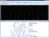
If the voltage step is small enough, around 200mV, the Xover artifacts disappear completely from the distortion residue, as the oscillogram showed.To sum up: Q1 will always conduct, even during its "quiescent" time, but the conduction of Q2 will be hard-switched, depending on the need: this is why the circuit is both switching and non-switching.
The switching aspect might seem to be a potential source of artifacts and discontinuities, but this is mitigated by the fact that Q1 remains always in conduction, thus keeping a certain control on the output, and the role of D1 to D3 is to reduce the magnitude of the discontinuity from ~3Vbe to 100 or 200mV.
It would be easy to keep both Q1 and Q2 in conduction all the time: simply add the N counterpart of Q3 to the base of Q2.
In reality, there is not much benefit in doing that: firstly, it consumes one Vbe on the non-bootstrapped side, reducing the output swing and the low-voltage operation ability, and secondly, it is not necessary: with a step of 100 to 200 or 300mV, the output is able to "ride over" the trough thanks to stored charge and similar effects, and the fact that the phenomenon is completely local, just confined between the collectors of Q3 and Q4, not relying on GNFB, thus very fast.
This is confirmed by the THD residue, where no Xover artifact is visible.
When one of the diode is shorted, small artifacts become visible on the waveform, but the global THD figure remains utterly unchanged.
Thus, it is important to minimize the step, and the magnitude of the step depends on the OP's temperature, which is why minimal thermal tracking is necessary.
Note that only the aspect of the residue is important as a criterion: you can have both 0.007% global THD and nasty spikes, because the energy of the spikes is very small.
Yes, I agree, and this worried me, but I couldn't find a way of eliminating it without additional complications, whilst keeping the other advantages intact: the ~1 to 10 supply range without changing a single component, for example.Not my favorite way to do a single supply voltage; I'm sure it has a serious turn on/off thump.
If you find a simple way of eliminating it without affecting the other features, I (and the DIY community) would be glad to see it.
Any other mod or improvement you can think of is also welcome
The project was designed according to Daniel's preferences, and he selected the transistors types and also provided their models.Your D44H11 model has a lot more gain than the standard LTC model, which is important for the single EF stage. With the standard model, you run out of current and get a premature positive clipping.
I would spend the extra $1 for current limiting, but that does increase the parts count.
In my build, I used the BD43x series, and they were suitable
I'm very grateful to see in-room-sized audio amplifiers in both fet and bjt. On parts, my preference is most common/availability, current production, and with accurized model available....And Daniel preferred it with no FETs....
Not so much fet avoidance, but separation is nice, because fets and bjt's are usually studied separately. Also, it is nice to make good use of the 19v or 24v smps; so that main focus stays at the amplifier board.
That model is one of Onsemi's D44H11/D45H11. They have many versions, just one of which matches the model. The good news is: vast availability....The project was designed according to Daniel's preferences, and he selected the transistors types and also provided their models....
If a different output were used, bigger is probably preferable, because modern speakers are 4 ohms or more load. So, I'd like to know which TO247 or TO3P or TO264 output devices you'd like? Here's two that are the most popular at diyaudio. Would one of them suit? And, if so, which is better for this amplifier?
https://www.onsemi.com/pub/Collateral/FJA4213-D.pdf or
https://www.onsemi.com/pub/Collateral/NJW0281-D.PDF
What I can tell from the datasheets is better tone than a chip amplifier, due to linearity. I can also tell that they're cheaper than small outputs because the big package outputs for small amplifier makes the heatsink costs disappear. But, I don't know the other details. So, it is a question.
P.S.
I love how strongly the application focus shows on the OldFashioned and EZmos amplifiers.
Also, if you combine EZmos mix-mono center with OldFashioned stereo pair, there is generous capacity to do very big audio show/presence without requiring excessive decibels to accomplish it. Although I had inquired about energy conserving, the dramatically increased effectiveness is an amazingly helpful way to do that. Kudos!
And, a question: Is the OldFashioned, actually a Class bG amplifier? I've never seen one before.
The 0281 is way better for low voltage operation. Compare the iIV curves. The C5200 types (all of them) have pretty significant beta drop at low Vce. Not what you want for something operating off 19 volts. That’s one of the advantages of the D44/5 types - good gain out to 10 amps at 1 volt. You do pay for it in poor SOA, but you only need full power to 9.5 or 12 volts Vce anyway. They used to use the giant TO-92s in amps like this back in the day. With a regular 2-diode bias stack, of course. If I was going to run it off 6 or 12 volts that’s what I’d be inclined to use.
The transistors you gave as examples have a Vce of 250V: that is ~10times what is required for this type of amplifier.If a different output were used, bigger is probably preferable, because modern speakers are 4 ohms or more load. So, I'd like to know which TO247 or TO3P or TO264 output devices you'd like? Here's two that are the most popular at diyaudio. Would one of them suit? And, if so, which is better for this amplifier?
https://www.onsemi.com/pub/Collateral/FJA4213-D.pdf or
https://www.onsemi.com/pub/Collateral/NJW0281-D.PDF
Inevitably, a high Vce negatively impacts the Hfe, even if they are quite good, something like 100.
You need a low-voltage (<40V) transistor optimized for high-current, high Hfe application, but finding them in a large case, TOP3 or TO247 is going to be difficult.
There are probably Japanese types, with perforated emitter having a low Vce and high Hfe, but most are going to be in a smaller case because a high power is not justified.
The old superbeta 2SC1984 would be ideal, except it is in a TO220 (and I don't know any official complement)
Thanks for the parameters! I'll go look at TO220 and TO263, in comparison to.... oops! I forgot which variant of D44/45H11 to use....You need a low-voltage (<40V) transistor optimized for high-current, high Hfe application, but finding them in a large case, TOP3 or TO247 is going to be difficult. There are probably Japanese types, with perforated emitter having a low Vce and high Hfe, but most are going to be in a smaller case because a high power is not justified. The old superbeta 2SC1984 would be ideal, except it is in a TO220 (and I don't know any official complement)
Well, then the shortcut?? looks like this:
Vast availability is good, but cost some confusion with the shopping. Then, the relevant question is, which of these do you like?
ON
https://www.onsemi.com/pub/Collateral/D44H-D.PDF
https://www.onsemi.com/pub/Collateral/MJF44H11-D.PDF
https://www.onsemi.com/pub/Collateral/D44VH-D.PDF
https://www.onsemi.com/pub/Collateral/NJW44H11-D.PDF
https://www.onsemi.com/pub/Collateral/2N6487-D.PDF
Fairchild
https://www.onsemi.com/pub/Collateral/FJAF4210-D.pdf
https://www.onsemi.com/pub/Collateral/FJAF4310-D.pdf
https://www.onsemi.com/pub/Collateral/KSE44H-D.pdf
https://www.onsemi.com/pub/Collateral/KSE45H-D.pdf
ST
https://www.mouser.com/datasheet/2/389/d44h8-954605.pdf
Sanken (parametric)
https://www.digikey.com/products/en...41&page=1&stock=1&rohs=1&nstock=1&pageSize=25
Gosh that's a big list, but I'm daft on which to use.
Some problem with the small devices and chip amplifiers as well--output losses acceptable with 16 ohm or 8 ohm speakers. Good yesterday. But not today--there's been a change.The 0281 is way better for low voltage operation. Compare the iIV curves. The C5200 types (all of them) have pretty significant beta drop at low Vce. Not what you want for something operating off 19 volts. That’s one of the advantages of the D44/5 types - good gain out to 10 amps at 1 volt. You do pay for it in poor SOA, but you only need full power to 9.5 or 12 volts Vce anyway. They used to use the giant TO-92s in amps like this back in the day. With a regular 2-diode bias stack, of course. If I was going to run it off 6 or 12 volts that’s what I’d be inclined to use.
Currently we can expect inefficient 4 ohm speakers in a smaller cabinet that will also incur a bass boost from the source. Takes a bit more push and higher-linearity outputs, to make up for the modern speaker situation.
Probably, this is the least sketchy wish-list or application parameter that I sent to Elvee somewhere in one and a half pages long list. Sure is awesome that he answered that with not just one but two amplifiers for it. Small room (the majority) audio, and WOW! the application focus is right on.
P.S.
Thanks for the news on the 0281 vs 5200. I'll cross-quote you at the TGM8-Retro25 thread where there was some question about which of those two outputs.
You need a low-voltage (<40V) transistor optimized for high-current, high Hfe application, but finding them in a large case, TOP3 or TO247 is going to be difficult.
There are probably Japanese types, with perforated emitter having a low Vce and high Hfe, but most are going to be in a smaller case because a high power is not justified.
The old superbeta 2SC1984 would be ideal, except it is in a TO220 (and I don't know any official complement)
The D44H is available in TO-247. Unfortunately, the D45 is not. Never was, never will be.
Some of those Jap types you refer to are still being made by ON (acquired from Sanyo). Low volt, high hfe, high fT, but no PNP... and TO -220.
If you could get it working with alll NPNs without losing one or two more vbe we would be getting somewhere. That’s your next challenge, I guess.
It would also be possible to use a mix of Si and Ge transistors, as some early complementary amplifiers did, for example a 2N456 as a PNP and a 2N3055 for the N side.
A perfect steampunk project...
I propose Bs/i, for switching/idling, as both regimes are present
A perfect steampunk project...
No, there is no class G there, only class B.And, a question: Is the OldFashioned, actually a Class bG amplifier? I've never seen one before.
I propose Bs/i, for switching/idling, as both regimes are present
Not a too difficult one, except it uses up one more transistor:If you could get it working with alll NPNs without losing one or two more vbe we would be getting somewhere. That’s your next challenge, I guess.
Attachments
Fear not, your not alone. Lol😀I try to use dumpster/hellbox parts as a challenge for fun.
My Scrap parts stereo project
 🙂
🙂Bootstrap is a glorious concept! And as I can see, is under implemented in SS audio, as are J-fets.😛
No, Daniel is more interested in the EZmos design, so no evolution here.
I have also developed the "big brother" of the Old Fashioned, and if someone is interested, I might publish it.
I have also developed the "big brother" of the Old Fashioned, and if someone is interested, I might publish it.
Please publish the " big brother" also! Particularly, at +50 Volts, DC and with output Capacitor.
Wonder if there has been any progress with this design?
I posted my version of "auto-bias" on another thread, only to see it molested by the contributions of others who missed the point completely. I just let it go. You can't help some people.
I'm interested in new solutions to classic problems and recently besides (1.) auto-bias, I was impressed by the (2.) VAS output voltage offset (~bootstrap) used in EZMOS since it eliminates standard MOS vto saturation.
And (3.) some time ago I came up with an all-NPN output using a current mirror that would be great for monolithic amps, but like other amateurs, I'm not about to start making chips.
I also found that you can (4.) partially bootstrap the whole VAS and drivers but you have to beware of MOS current transients coming out of rail sticking.
A trick I quite like is (5.) "floating" ground for single supplies. Years ago I needed a quick amplifier for a music/intercom system and I had some ~Sinclair single supply clone boards, so I ran a bell transformer through two diodes for two half wave rectifiers and returned the speakers to the intersection of the two supply caps. It works well and multiple channels can share. If you had only one channel, it would be DC proof like QSC.
I'm not impressed by kilo-Watt amps, even when they are well done. The only people who need such a thing are professionals and professionals just buy professional amps. High power needs to be class-D, IMHO.
So thanx LV, you are on my short list of interesting posts.
The bigger brother can be found here:
https://www.diyaudio.com/forums/solid-state/341721-fashioned-amplifiers-twist-2-a.html#post5890688
https://www.diyaudio.com/forums/solid-state/341721-fashioned-amplifiers-twist-2-a.html#post5890688
Elwee can I ride? I need OTL for my Vintage Philips and I'm looking for something basic with lower THD.No, Daniel is more interested in the EZmos design, so no evolution here.
I have also developed the "big brother" of the Old Fashioned, and if someone is interested, I might publish it.
- Home
- Amplifiers
- Solid State
- Old-fashioned amplifiers with a new twist (1)