Would there be any effect on performance or operation by adding emitter resistors?
Very interesting design Elvee. Are there other suitable commonly available output devices you can suggest?
Very interesting design Elvee. Are there other suitable commonly available output devices you can suggest?
Emitter resistors add local negative current feedback, then if emitter current tend to increase above certain value, be it by overload or output shortcicuit or thermal runaway, resistor voltage drop counteract to signal input, reducing transistor stress.
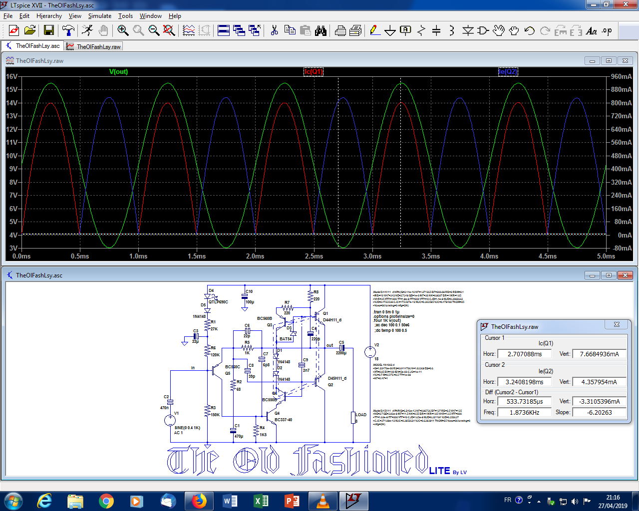
I had repaired lots of old fashioned amps like the classic AD161-162 pair, the quasi made from AD149, and so on, and no led's at all...
Hi,
I guess that in times when Ge power devices were still high in fashion, LED's hadn't been invented, or at least brought into the commom market yet.
Best regards!
How come nobody noticet that Mr. L.V. really knows his **** in and out? He's using BD435/436 pair in his prototype. A known low-loss family, custom tailored for low-power output devices. A blast from the past, from the "good old times"!
Btw why don't you use something a liiiittle heftier like a BC327 as a Q3?
Btw why don't you use something a liiiittle heftier like a BC327 as a Q3?
Not really: remember, contrary to appearances, this is not class AB, and applying classical AB recipes to this circuit will not have the usual results.Would there be any effect on performance or operation by adding emitter resistors?
Although the circuit will perfectly tolerate resistors, they are unnecessary, and if the "bias engine" does not work properly, destruction will occur anyway.
At most, if the diode string is inadequate, they could slightly reduce the risk of thermal runaway, and other than that, they will be decorative and will deprive you of one of the interesting feature of this topology: the zero I*R losses.
For example, you won't be able to use this truly rail-to-rail variant:
It is just a simulation, and transistors, compensations, etc. have not been updated, but it shows you the principle, and it could certainly be made to work in reality.
Anti is perfectly right:Very interesting design Elvee. Are there other suitable commonly available output devices you can suggest?
You need high Hfe, low saturation devices, and transistors originally intended for car-radio amps are perfect: BD329/BD330 are similar.He's using BD435/436 pair in his prototype. A known low-loss family, custom tailored for low-power output devices. A blast from the past, from the "good old times"!
The D44/D45 pair is also suitable, and many more modern, high-perf devices could also work well.
You need a good Hfe, because the OP is based on singles, and you want to minimize the current in R7 & R8, and the VAS/driver
Q3 is subjected to a maximum current of a few tens of mA, and its dissipation will be negligible because its Vce is going to remain very small, 1V or so, and for this current range, the BC557 probably has a slightly higher Hfe than the BC327, but a BC327-40 would also work perfectly.Btw why don't you use something a liiiittle heftier like a BC327 as a Q3?
If you intend to use this amp at relatively high voltages (>24V), Q4 would benefit from being a somewhat larger type.
The resistors R7 & R8 should also have a larger rating than 0.25W
Attachments
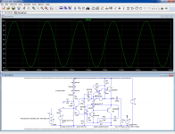
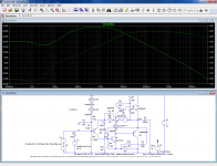
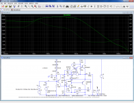
You are right, the phase has a funny look:
Apparently it is caused by the lower bootstrap making C7 mostly ineffective.
If R11 is defaulted to 1m, most of the strangeness disappears:
As I said, this is an earlier version I didn't optimize and didn't try in reality, and the compensation strategy would need to be adapted and optimized.
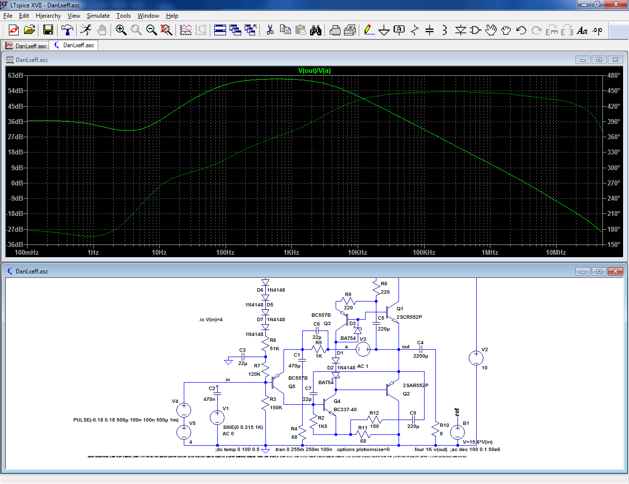
That said, the FR does not show any peaking, and the squarewave response with a small timestep looks perfectly clean, with no sign of ringing:
A paradox, that would need to be investigated in the real world, because the sim does not seem very useful in this case
Apparently it is caused by the lower bootstrap making C7 mostly ineffective.
If R11 is defaulted to 1m, most of the strangeness disappears:
As I said, this is an earlier version I didn't optimize and didn't try in reality, and the compensation strategy would need to be adapted and optimized.
That said, the FR does not show any peaking, and the squarewave response with a small timestep looks perfectly clean, with no sign of ringing:
A paradox, that would need to be investigated in the real world, because the sim does not seem very useful in this case
Attachments
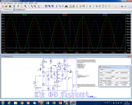
Here are two additional variants that I have studied in sim only and may consequently need to be updated regarding the compensations and some others aspects.
One uses a Rush cascode and zener level-shifter to increase the loop gain, and lower the THD:
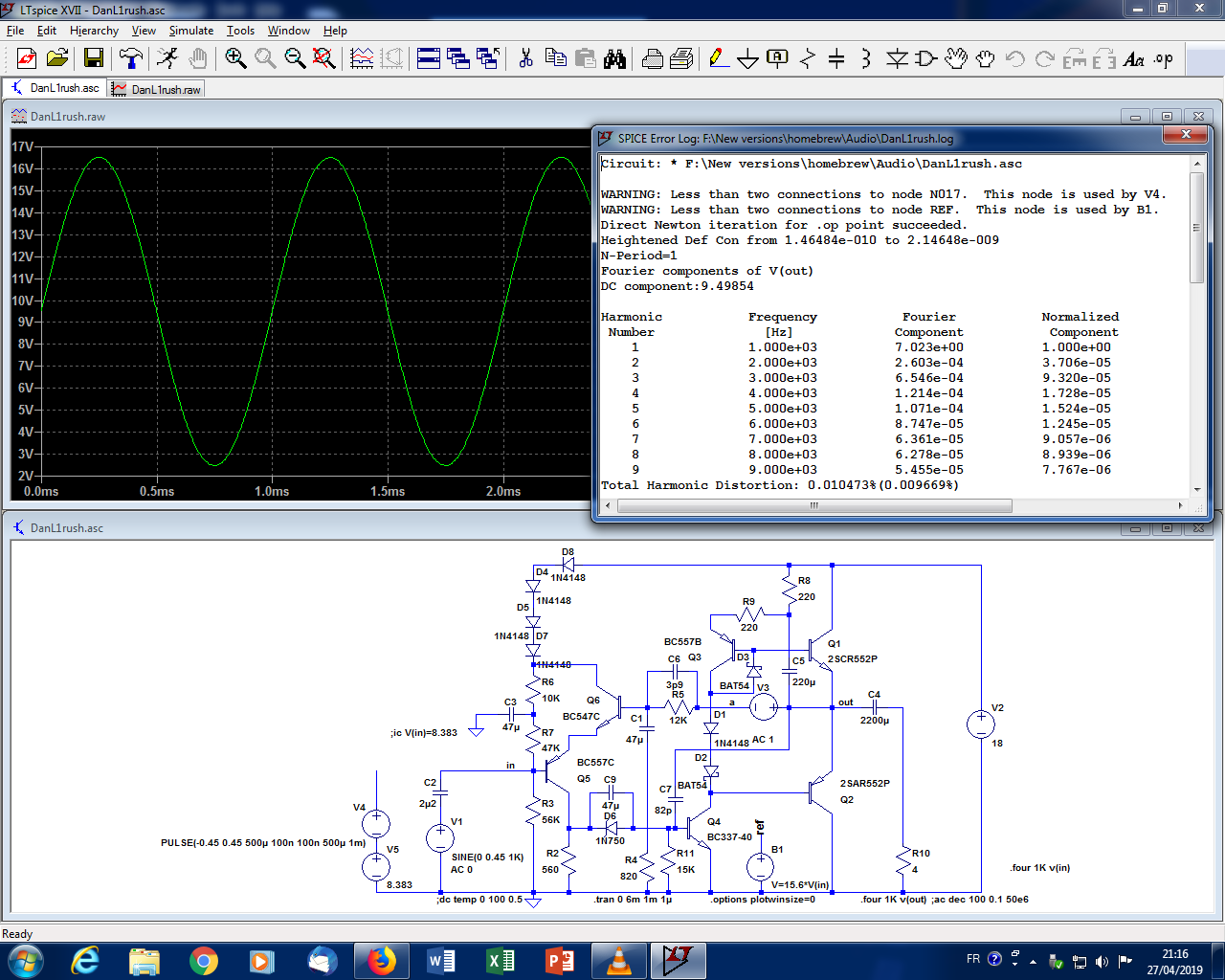
The other shows the symmetrical version of the bias I mentioned, and although it has not been tested physically on this exact circuit, I am pretty sure it will work as advertised, and it is in fact a purely cosmetic mod, which is why I grafted it directly onto the "clean" schematic:
Although it is symmetrical and keeps both OP transistors "alive" at all times by imposing a small minimal current (here, ~7mA and 4mA, defined by the Hfe ratio of Q1 to Q3 and Q2 to Q6, as usual), which in principle should be "Good Things", all aspects of the behavior and performance remain mostly unchanged, except that the negative swing is amputated of 1 Vbe, which could matter for low supply voltages.
Diodes D1 and D2 can now be ordinary 1N4148's, because there is a bit more room for maneuver.
Edit:
I forgot to use an antisaturation schottky on Q6
One uses a Rush cascode and zener level-shifter to increase the loop gain, and lower the THD:
The other shows the symmetrical version of the bias I mentioned, and although it has not been tested physically on this exact circuit, I am pretty sure it will work as advertised, and it is in fact a purely cosmetic mod, which is why I grafted it directly onto the "clean" schematic:
Although it is symmetrical and keeps both OP transistors "alive" at all times by imposing a small minimal current (here, ~7mA and 4mA, defined by the Hfe ratio of Q1 to Q3 and Q2 to Q6, as usual), which in principle should be "Good Things", all aspects of the behavior and performance remain mostly unchanged, except that the negative swing is amputated of 1 Vbe, which could matter for low supply voltages.
Diodes D1 and D2 can now be ordinary 1N4148's, because there is a bit more room for maneuver.
Edit:
I forgot to use an antisaturation schottky on Q6
Attachments

Last edited:
You can sometimes get the weirdest loop gain and phase plots when an amplifier is unstable with open loop due to a local positive feedback. Apply a negative feedback that's stronger than the local positive feedback and everything behaves normally again.
Yeah but what happens if you play loud and clip the amp here and there. For low-voltage amps I think it's better to make it as flat as possible. Otoh, a low-voltage-wattage amp won't do much damage if it burps here and there...
BTW, nice touch-ups on topologies from the younger days, he he.
BTW, nice touch-ups on topologies from the younger days, he he.
Small-signal stability doesn't guarantee large-signal stability, but that's true with or without local positive feedback loops.
Indeed, which is why I did a large signal squarewave test (in sim).
The ultimate acid test would be the reality, something I may try as it would test how far simulations can be trusted
The ultimate acid test would be the reality, something I may try as it would test how far simulations can be trusted
I made the test, the quick-and-dirty way: I just grafted the bootstrap components to the latest version to make it rail-to-rail.

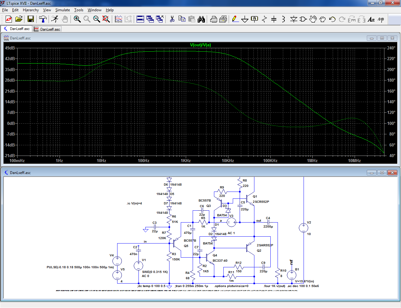
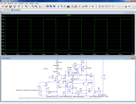
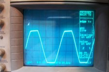
That aspect works as expected, which is no surprise, and I tested the 10kHz, large signal squarewave behavior:
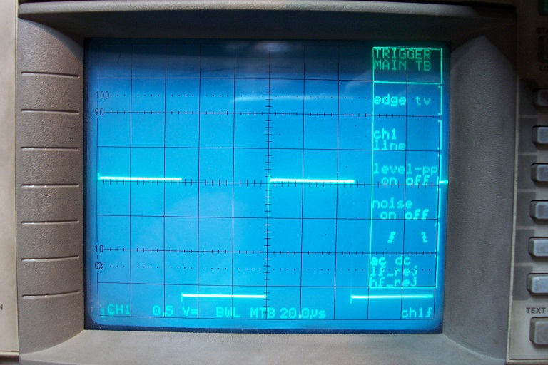
The result is slightly degraded: a small overshoot.
Nothing catastrophic, and it can be remedied by bypassing R11 with a 5 ~10nF cap, and/or increasing the compensations according the division ratio of R11 and R12, so it is usable. I didn't attempt to refine the compensations to the point of perfection, but it should be doable (you could even live with the small overshoot: on actual music, the effect should be infinitesimal).
Without a load, the signal is perfect.
That aspect works as expected, which is no surprise, and I tested the 10kHz, large signal squarewave behavior:
The result is slightly degraded: a small overshoot.
Nothing catastrophic, and it can be remedied by bypassing R11 with a 5 ~10nF cap, and/or increasing the compensations according the division ratio of R11 and R12, so it is usable. I didn't attempt to refine the compensations to the point of perfection, but it should be doable (you could even live with the small overshoot: on actual music, the effect should be infinitesimal).
Without a load, the signal is perfect.
Attachments

Have you tried driving it into clipping and checking that it recovers? If there would be a large-signal stability issue, you would probably see it only when you drive something into clipping.
Yes I did, and a small degradation also appears (slight rail-sticking), but again nothing near as catastrophic as the loop analyzis would hint at.
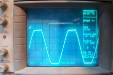
Here is the behavior of the "normal" configuration:

And here it is with the bootstrap and nothing else:

The same remedies that cure the squarewave misbehavior also work on that one
Here is the behavior of the "normal" configuration:
And here it is with the bootstrap and nothing else:
The same remedies that cure the squarewave misbehavior also work on that one
Attachments
I feel good.
BTW did you try to bootstrap the vas directly from the speaker output? Does it play nice or is the added 220uF cap necessary?
BTW did you try to bootstrap the vas directly from the speaker output? Does it play nice or is the added 220uF cap necessary?
Last edited:
No, I didn't try it and I am confident it will also work, but with some DC current through the speaker, something cheap, early amplifiers tolerated some decades ago, when the cost of E-lytics was not negligible.
Nowadays, that is something that is in general badly regarded and unnecessary, but it will offset slightly the rest position of the voice-coil, and create additional even-order distortions, something people seem to find pleasing (don't count me in)
Nowadays, that is something that is in general badly regarded and unnecessary, but it will offset slightly the rest position of the voice-coil, and create additional even-order distortions, something people seem to find pleasing (don't count me in)
Interesting circuit, I'm always looking for nice discrete designs for use in a doomsday situation.
Will study some more.
One of the best amps I've ever heard had a output cap.(early Pioneer)
Will study some more.
One of the best amps I've ever heard had a output cap.(early Pioneer)
- Home
- Amplifiers
- Solid State
- Old-fashioned amplifiers with a new twist (1)