Iron powder core for output sound ok as far as I know
But I don't know why you have 2 inductors after etd, that should be one and after diods, I hope you have it like that
But I don't know why you have 2 inductors after etd, that should be one and after diods, I hope you have it like that
hi luka ,
is it ok now
http://img153.imageshack.us/img153/4706/88772179.gif
isnt it primatry providing more current then secondary.
thanks
ravs
be a vegeterian.....
is it ok now
http://img153.imageshack.us/img153/4706/88772179.gif
isnt it primatry providing more current then secondary.
thanks
ravs
be a vegeterian.....
yes, if secondary voltage is higher then +/-160vdc in case of 230Vac input
Its better, but this goes for any trace around primary, secondary... see that top right pin of SG that is connected to... that one is close to secondary, while SG is part of primary circuit
Its better, but this goes for any trace around primary, secondary... see that top right pin of SG that is connected to... that one is close to secondary, while SG is part of primary circuit
Last edited:
depends on voltage (size of cap), you can calculate what value you will need for your design (ripple current).What size and value of caps would recommend to both of us, Luka?
If all that is too much, go for about 3000uF max per rail, that means 3-4 caps. unless you can get low esr caps, then you can get away probably with even less... everything else is done with regulation, if that is what you go for, as I think you do. I can not stress enough, how important compensation is. If done right, you have almost perfect DC on output, independent of load you have
I am going to go with 4 CHEAPO 1000uf 100V per rail, then AFTER I build and test it I can take out as much as I can get away with.
The board I am laying out is just to test out everything I want to do before I commit to making a few clones of them...
IS there a site or something that I can use to calculate the inductors based on turns wire gauge material etc... I need to learn that too, what do you recommend...
Thanks
The board I am laying out is just to test out everything I want to do before I commit to making a few clones of them...
IS there a site or something that I can use to calculate the inductors based on turns wire gauge material etc... I need to learn that too, what do you recommend...
Thanks
note that less is more with switching supplys, no need for bulk capacitance, only on primary if you don't use pfc, on primary I say as much as you can
Site... don't know, but there are several books on this topic
Site... don't know, but there are several books on this topic
size on primary, you want as many uF as you can get on board, 60Hz(120Hz) you can't filter on output, so better there is noneOkay I got you... I am down to 2 on out put and up to 4 on INPUT
Which books? Basso? ???
Abraham Pressman - Switching Power Supply Design 3rd Edition
Ron Lenk - Practical Design of Power Supplies
Marty Brown - Power Supply Cookbook (2nd ed.)
COLONEL WM. T. MCLYMAN - Transformer And Inductor Design Handbook, Third Edition
and
DESIGNING MAGNETIC COMPONENTS FOR HIGH FREQUENCY DC-DC CONVERTERS, also from him
I mean, there is over few 1000 pages, if you really want to learn 😀
Any of those available ON LINE
I just ordered 4 390uf at 450 Panasonic's from the coast...
Thanks a lot
I just ordered 4 390uf at 450 Panasonic's from the coast...
Thanks a lot
most you can get on google...if not PM and will talk
anyway, why 450v? you aren't making full bridge, are you? 200v would be more then enough, and about 1000uF per cap
anyway, why 450v? you aren't making full bridge, are you? 200v would be more then enough, and about 1000uF per cap

amm well, will it be 110 or 220? FB can't be both, not without PFC, unless you will have 2 diffrent trafos, depending on what voltage it will be for
Then give me a hint on how to implement PFC and I will include it in my BOARD.
Thanks for your help
Thanks for your help
So I can insert the PFC after the rectifier and caps on the input before I feed the DC to the full bridge... is that about it?
Thanks
Thanks
you can put it on normal AC input, where you would put 110Vac, so you have same supply, but this time you don't feed it with ac, but with 400Vdc or what ever voltage you will go for in the end
you can check for PFC on my site, it had no problem supplying my half bridge, which worked 10x better then without PFC in front. As bonus you get from adding PFC, are:
pretty much only DC, constant voltage, you can use if from LOW to HI mains input, regulation is ultra solid, even if unregulated supply, output is very constant, very high power factor,...
OK
what are the specs on the transformer?
Do you have any pictures of your unit, or a pcb layout?
Thanks, this seems like just what I need...
Thanks
what are the specs on the transformer?
Do you have any pictures of your unit, or a pcb layout?
Thanks, this seems like just what I need...
Thanks
I have and I don't, point is, I still didn't took time to post more on site
PCB is 86mm x 95mm big (3.385" x 3.74").
I would still need to change output diod, for some that I can put on heatsink. I had no problem (apart from too much heat from two MUR4100) getting 1kw DC, constant power, ok input bridge rated 4A had also 4Aac+ going into it, so that could be changed too
As always, there will be PCB and pictures provided, schematic is standart one from datasheet, so that is already up
About trafo, well I think its all written from what I know, it was from pretty old and big PC supply, that even back then was rated at 500w, main trafo is still waiting to be disassembled, first time around was a no go. I am pretty sure PFC inductaor has air gap inside, it is made of litz wire, and has a secondary on it
Last edited:
t
heatsink is:
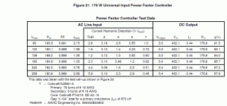
This is from the application note on the MC34262
http://www.onsemi.com/pub_link/Collateral/MC34262-D.PDF
Thanks
heatsink is:
This is from the application note on the MC34262
http://www.onsemi.com/pub_link/Collateral/MC34262-D.PDF
Thanks
Attachments
- Home
- Amplifiers
- Power Supplies
- Offline full-bridge SMPS… need help