Yes ,you are right I have seen the program mentioned on LTspice forum and I understand they have a large user group.I use a commerical program that does up to 32 layers(big deal I try never to use more than two except for smd combined with THT.
Hello, I have made the version 6 smps of equal Luka to the original scheme and it does not start the SG3525, which can happen?
This question should be address to Luka but I might offer a few suggestions:
Do you have a scope?
The first thing is I would double check my work including correct parts and proper soldering of all joints ,no broken or burnt resistors or other parts ,check the VCC voltage to assure startup circuit is working,remove mosfets,IR2010 and check pin 4 of SG3525 should have an almost square waveform of 5volts at a frequency of about 100kHz,disconnect any components from pin 10 and then check output at pin 11 and 14 for waveforms that indicate SG has output,check pin 16 for 5 volts.I hope this helps refer to SG3525 datasheet there is a test setup to test the function of the IC,you should be able to duplicate most of it with the chip in the circuit.I always check the controller part of a supply before mounting transformer,mosfets,diodes and bridge circuit.I think a DIY supply should be designed so the control circuit can be verified first without any bulk supply which can done by fusing this circuit,remove fuse use battery or other low voltage source to supply power,you can also supply feedback with battery to check pwm.
Last edited:
check that after startup transistor there is more then 10v (you can check this on supply pins of SG), also that pins 1 and 9 are connected
maybe you can post pictures of top and bottom of the pcb, as is now
maybe you can post pictures of top and bottom of the pcb, as is now
Hello, it was what was absent, to join pin 1 and pin 9, it is not in the PCB, but if in the scheme.
I did it on the part of below of PCB.
I have + 60,9 and - 61,9 in exit, use EDT44, which it Power obtendre with this one?
Thank you very much
I did it on the part of below of PCB.
I have + 60,9 and - 61,9 in exit, use EDT44, which it Power obtendre with this one?
Thank you very much
Last edited by a moderator:
I would say its not coz it has high voltage drop of 2.25v, pretty large gate C, apart from those 2, you can yesG4PF50WD is this Good for this project? or is there a better choice out there?
Look for no more then 500v igbt's or fets
Last edited:
Indeed, I have wire on pcb, you could put it under IC also...Hello, it was what was absent, to join pin 1 and pin 9, it is not in the PCB, but if in the scheme.
I have + 60,9 and - 61,9 in exit, use EDT44, which it Power obtendre with this one?
Thank you very much
well start putting load on to it, like I said, 500w should do with no problem. Do you have secondary aux also?
No problem, post pictures then you have it done
Last edited:
I am going to put 1000uF 200v at the entry, in the exit I have 2.200uF 63v.
I have IRFP460, the equal rest to the version 6, Have aux secondary, but that tego that to try to change resistances since it does not start me this way. I will raise photos shortly.
Thank you very much for the help
I have IRFP460, the equal rest to the version 6, Have aux secondary, but that tego that to try to change resistances since it does not start me this way. I will raise photos shortly.
Thank you very much for the help
Attachments
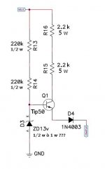
Vbus is 230v ac rectified, about 330Vdc, and since this is half bridge, it uses 2 200v capacitors in series, I used 470uF, but should 1000 or even more, so do use 1000uF ones. How does it then start?
I used 680R, R15,R16 and this should be enough. If I remember right, IR + SG and all things on need about 50 to 55mA and above ~9v for sg to start. so even with 2.2k for this resistors you would still have enough current to start it with out a problem.
one thing you can test is, put a 470k resistor in parallel to R13 and R14 (cross both). This will open TIP50 more(it will output more current)
But after SG starts, aux should make voltage higher then STARTUP is, and will taka over supplying the IC's
From the start I used external supply to supply 13v to SG (didn't had start up circuit then)
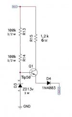
this circuit works only 1 or 2 seconds if that.
But if it doesn't, those 5w resistors and tip55 have to take the power, and heat up really fast (can't work without aux, more then few seconds)
if nothing heats up, circuit is working as intended
But if it doesn't, those 5w resistors and tip55 have to take the power, and heat up really fast (can't work without aux, more then few seconds)
if nothing heats up, circuit is working as intended
http://www.diyaudio.com/forums/atta...full-bridge-smps-need-help-schemat-nowy-2.pdf
hi guys i used the above protection using a resistor . there was voltage formed across resistor but never shut down the sg 3525 . finally when the resistor failed it destroyed the ir + sg ics . does any one have a simple protection scheme which does not use former i.e similar to car amps. thanks steve
hi guys i used the above protection using a resistor . there was voltage formed across resistor but never shut down the sg 3525 . finally when the resistor failed it destroyed the ir + sg ics . does any one have a simple protection scheme which does not use former i.e similar to car amps. thanks steve
I wonder if there is a vendor that would make a transparency of a pcb layout from Gerber files for a small fee, then mail the transparency to me. I tried to Google it without any luck.
Does anyone know of such a company?
I want to do double sided boards about 12 by or so.
I can drill the holes with a dremel tool.
Does anyone know of such a company?
I want to do double sided boards about 12 by or so.
I can drill the holes with a dremel tool.
hi luka i,m from testing the smps .i tried bridge mode with 100wts bulb in series ac but it was drawing a lot of current. then i switched to the half bridge . it is working ok and drawing less current . i,m quite shocked of how cool the mosfets (450) are compared to the transfomer gate drive i was using previously .i used your first design where i had to use a small 12v former maybe later i,ll try the new design 🙂 i gave up on protection so i haven't included any . BTW i did it on a strip board if i find the the photo diag of etching i'll etch. may GOD bless you and all who participated in the design and your efforts stewin
you can always add some kind of protection, so this should not be the most important thing you do
Krisfr
If you get the pcb of Luka's supply from this thread and print it on a laser printer,take to any printshop,Kinko's or other even your high school photolab can make you a negative or a postive transfer(make sure its a mirror image)Hold the pcb up to a light source to check.Then you can process it and start soldering parts.
If you get the pcb of Luka's supply from this thread and print it on a laser printer,take to any printshop,Kinko's or other even your high school photolab can make you a negative or a postive transfer(make sure its a mirror image)Hold the pcb up to a light source to check.Then you can process it and start soldering parts.
- Home
- Amplifiers
- Power Supplies
- Offline full-bridge SMPS… need help