Hi
Not that discrete level-shifter is in any way bad, but it just complicates the design, ICs and xfmr use less space on board and are less messy, and you know exactly what will happen if you do this or that. Where with discrete you must check if that is opened enought, is voltage present where it shouldn't be,.... takes too much time, wich you could spend doing other things.
IR's are a bit expensive here about 5,34 € if you can even say expensive, but that is not that bad if it works as it did(is still 😉) for me.
IR's are a bit expensive here about 5,34 € if you can even say expensive, but that is not that bad if it works as it did(is still ) for me.
Hi,
I've been finding that I can use the IR2112 for things I build now. I wonder if they are cheaper than the high current ones there like they are here. I agree that convenience and simplicity are worth a little cash.
luka said:Hi
If external clock for SG is 125kHz then SG will work with 62.5kHz?
Hi Luka,
I think so, since the SG3525 has a divide-by-two internal set-up. It uses a flip-flop. It is the one reason why I can't use that chip in my ZVS circuits. I also like a controller circuit which draws very little power so that power bootstrapping isn't needed. Another thing I need are IC chips available in dip packages.
I have to keep putting in plugs for the USMPS because I think if people understand it they will like it. I do it just for its usefulness for folks and I have no commercial or profit interest. Have you ever looked at it?
Electrone,
Have you ever looked at the Philips TEA1610T P 1 chip? It is a ZVS resonant-mode chip with the HVIC stuff on board. No separate control and driver chips anymore. Go to philips' website for more info. Or, if you want to use the supply of IR2112s you have on hand, try this chip: MC33067 by ONSemi. It is a 2-channel ZVS resonant-mode chip for use in either AC-DC or DC-DC converters. Oscillator freq is good to 2.2MHz.
HTH,
Steve
Hi Steve,
I have looked at the TEA1610 chip especially because of its relative simplicity. But I opted for another way. One main reason is that I wanted to be able to simulate close approximations of the real circuits, and the USMPS is good that way.
The MC33067 looks rather complex in comparison to the universal approach I believe I have established through the ZVS USMPS circuit. I like the IR211x family of chips and would like to keep using them. Well, I'm giving you a hard time today. 😱 The main reason I use ZVS is to reduce harmonic content at high frequencies. I try to use the lowest switching frequency I can. I am not intending to be Luddite, but I have found an approach that I really believe in, especially for the DIYer, and I consider myself one.
outstanding luka! i was looking for your latest schematic....
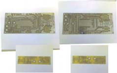
my boards will be here next week, finally sold enough other things to pay for them......
my boards will be here next week, finally sold enough other things to pay for them......
Hi
I will make new one, the one that I currently use and post it on my website and here.
Can't wait to see your boards, as you probably can't 😀, so keep me posted how things are going.
I will make new one, the one that I currently use and post it on my website and here.
Can't wait to see your boards, as you probably can't 😀, so keep me posted how things are going.
Hi
Now cames the better part, building it. Sorry for not posting my schema yet, still didn't finished changing my mind, what will be on.
I'll do that as soon as possible(made up my mind in proces 😀)
Now cames the better part, building it. Sorry for not posting my schema yet, still didn't finished changing my mind, what will be on.
I'll do that as soon as possible(made up my mind in proces 😀)
Hi
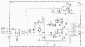
Here is my schematic for final board, hope that I have everything on board and on schematic.
It is HB, with output at about +/-47v and AUX +/-12v
It is regulated and operates from mains (offline).
With Etd44 it is easly good for up to 550w @ 50kHz
Any comments, pls let me know, or if I made any mistakes on schematic.
Lp, Luka
BTW: Last time...
Attachments
ps
Luka
Nice work, you might want to correct you schematic for your inductor if it is on the same core the dot ends should oppose each other, It looks like the intention of this is to supply a classd, if so have you tested it or simulated it? The inductors are small I think for your fsw and load requirements also you might be in DCM for a long period of time and buss pumping will be a problem unless you amp is fullbridge. You might want to look at compesating the TL431 a couple of poles are involved that could cause some grief if in DCM for long period's. I went thru this with mine before I changed over to a two switch forward converter, much simpler and well behaved.
chas1
Hi Chas
Thanks. This is my first time using Pcad, so I don't know how too fix things yet, but that is a must there so I will try to fix that.
It is for ClassD, didn't make board yet, I have done it in program, but still need to develop it. I should still put bigger output inductor? This woun't slow down reaction time of feedback, more like whole smps?Amp is half bridge, so buss pumping will be present, but can I reduce it if I would have bigger output inductor?
You don't have half bridge anymore? Can you post some pic of what you have now? Also at what freq. it is operating, output voltage, that sort of things.
Lp,Luka
A great find for all classd & smps DIYer's
Luka
This URL will direct you to a website where classd & smps are simulated and explained in great detail.http://www.genomerics.org/
chas1
Luka
This URL will direct you to a website where classd & smps are simulated and explained in great detail.http://www.genomerics.org/
chas1
Luka,
I took a quick look at you schematic and noticed a couple of things.
1. The voltage regulator circuitry seems incorrect. I don't think the TL431 circuit will work, and the connection of the SG3525 error amp and the opto is strange.
2. The ripple current through the 2.2uF cap in the transformer primary circuit will be quite large. Is the cap rated for it?
Rick
Hi sawreyrw
1. Rest asured, I have already tested TL connected this way, but it will only work so if SG is connected in such a way as show on schematic. I didn't believed it myself, but if other done it and it works for them, then I can assume that it will work for me too, wich it does.
2. Ripple is not that high for my power levels. This cap is MKT and I have already tested it to 800w with no problems. It is certainly rated for such use.
Read here for what they are used
Lp, Luka
Hi Luka,
I've just found an interesting smps schematics: YAMAHA YST SW800
something like 1kW without any ic driver, just discrete approach (6 bipolar transistors) switching @40kHz i Think.
I would like to try it what do you tink about it ?
I'd like to try it with a FT240-77 core...
I've just found an interesting smps schematics: YAMAHA YST SW800
something like 1kW without any ic driver, just discrete approach (6 bipolar transistors) switching @40kHz i Think.
I would like to try it what do you tink about it ?
I'd like to try it with a FT240-77 core...
Attachments
Hi
If you want to build it yourself, I don't know. This is selfoscilating and is the most difficult to make it work right. It sure looks good, but I don't recommend it. And it is unregulated. Transformer is a key to make it work. It produces main power, but also transistors drive. I wanted to make one such as this, even if for low power. But I have been convinced otherwise by guys/girls here that know thing or two about this king of smps.
If you would like to buy one, I hear that smps from coldamp is great for damps
Hi Luka,
What about your D AMp ;-) ?
I made a few unregulated smps but i got the same problem as you : great secondary voltage drop under heavy load condition
don't know why.
I'm not convinced by regulated designs...
IR2113 driver doesn"t seem to be as reliable as gate drive transformer so gonna make a new smps with this kind of gate drive transformer
- Home
- Amplifiers
- Power Supplies
- Offline full-bridge SMPS… need help