gate drive
jamesrnz
The appnotes of the pwm chip's contains suggested gate drive for different inputs and outputs and my understanding is if you don't ground the primary then a cap is not needed. As for zener's across the secondary I would use them to protect the mosfet. I have seen many circuits that contain only resistors but in a diy supply I don't like that approach.
chas1
Parallel Devices
Medogrizli
I am sure you have thought about this , when you parallel mosfets in an amplifier or any other design you concern is with matching because of current sharing and other problems, the gates have capacitance therefore it is possible that one might not turn off correctly which is a problem when you use a single device, today if you need more power you can use single IGBT's which are easier to work with than mosfets in MHOP. A halfbridge with todays IGBT's can be designed easily for output power around 1 kW also there are mosfets that can handle 12 amps with low RD on. Fairchild has some new device's check out thier website.
chas1
Re: Parallel Devices
Yes of cource I know all that bu there are some high current drivers UCC-- etc
This is JUST TWO mosfets in pararell : thats not so "bad" concerning capacitance
I think good designet ferit driver can drive two of them in paralell
So there is UCC that can "handle" 9A of current
1kW IS NOT problem using irfp460 : they are 20A I think : and for 1KW single I mean two of them for half bridge is enoguht : isnt it?
If You are from America: are you there is JUST 110V here is 220V and twice as much powwer I can get grom one 20A mosfet
(220*sqr2)/2 (half voltage cause of capaciotr in series)
thats 150V * 10A (a half that mosfet can handle) is 1550W
So there is no need for expensive IGBT for dwiving 1kW
What do you think?
Usually it is BETTER to make TWO SMPS of 1kW thank one of 2 kW
easier to get ferit core etc
chas1 said:Medogrizli
I am sure you have thought about this , when you parallel mosfets in an amplifier or any other design you concern is with matching because of current sharing and other problems, the gates have capacitance therefore it is possible that one might not turn off correctly which is a problem when you use a single device, today if you need more power you can use single IGBT's which are easier to work with than mosfets in MHOP. A halfbridge with todays IGBT's can be designed easily for output power around 1 kW also there are mosfets that can handle 12 amps with low RD on. Fairchild has some new device's check out thier website.
chas1
Yes of cource I know all that bu there are some high current drivers UCC-- etc
This is JUST TWO mosfets in pararell : thats not so "bad" concerning capacitance
I think good designet ferit driver can drive two of them in paralell
So there is UCC that can "handle" 9A of current
1kW IS NOT problem using irfp460 : they are 20A I think : and for 1KW single I mean two of them for half bridge is enoguht : isnt it?
If You are from America: are you there is JUST 110V here is 220V and twice as much powwer I can get grom one 20A mosfet
(220*sqr2)/2 (half voltage cause of capaciotr in series)
thats 150V * 10A (a half that mosfet can handle) is 1550W
So there is no need for expensive IGBT for dwiving 1kW
What do you think?
Usually it is BETTER to make TWO SMPS of 1kW thank one of 2 kW
easier to get ferit core etc
So about IGBT-s?
do they have gate capacitience like mosfets : if not : how much CURENT is needed to drive IGBT at 100kHZ ?
do they have gate capacitience like mosfets : if not : how much CURENT is needed to drive IGBT at 100kHZ ?
So did anyone HERE made SMPS usnig FERIT for driving MOSFETS : NOT like thise who use integrated hi and lo SIDE mosfet driver?
if so could I see schematics
p.s sorry for "tipfehlers" in the posts aove
if so could I see schematics
p.s sorry for "tipfehlers" in the posts aove
igbt's vs mosfets
medogrizli
Yes I have the option to use 110 or 220 VAC and the supplies I design can use both. The end result is going to be the same for both, the bulk supply after rectifiers will be about 300 - 380 VDC.
There is a debate ongoing about using igbt's rather than mosfets as switch's in supplies and the thinking seems to be under 100kHz and where high power is needed igbt's, above 100kHz mosfet's, as far as cost the mosfet and igbt is about the same here. Yes the igbt does have a capacitance you have to be concerned about but much lower than a typical mosfet .
The drive requirements are about the same, refer to the datasheet for the device you are going to use.
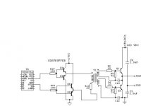
I am including one method of gate drive I use (see schematic) since you mention not using IC's to drive the high and low side switch.
The buffer is use to reduce the stress on the pwm chip.
chas1
medogrizli
Yes I have the option to use 110 or 220 VAC and the supplies I design can use both. The end result is going to be the same for both, the bulk supply after rectifiers will be about 300 - 380 VDC.
There is a debate ongoing about using igbt's rather than mosfets as switch's in supplies and the thinking seems to be under 100kHz and where high power is needed igbt's, above 100kHz mosfet's, as far as cost the mosfet and igbt is about the same here. Yes the igbt does have a capacitance you have to be concerned about but much lower than a typical mosfet .
The drive requirements are about the same, refer to the datasheet for the device you are going to use.
I am including one method of gate drive I use (see schematic) since you mention not using IC's to drive the high and low side switch.
The buffer is use to reduce the stress on the pwm chip.
chas1
Attachments
Re: igbt's vs mosfets
so can this drive u PAIR od irfp460 in paralell? I think so : do you?
i shoud experiment but I dont have n osciloscope😱
what is the purpose of C12 and C13 ? And why there are no zenner? Should I use them when uing mosfets? cause gate max +/- 16V
chas1 said:medogrizli
Yes I have the option to use 110 or 220 VAC and the supplies I design can use both. The end result is going to be the same for both, the bulk supply after rectifiers will be about 300 - 380 VDC.
There is a debate ongoing about using igbt's rather than mosfets as switch's in supplies and the thinking seems to be under 100kHz and where high power is needed igbt's, above 100kHz mosfet's, as far as cost the mosfet and igbt is about the same here. Yes the igbt does have a capacitance you have to be concerned about but much lower than a typical mosfet .
The drive requirements are bout the same, refer to the datasheet for the device you are going to use.
I am including one method of gate drive I use (see schematic) since you mention not using IC's to drive the high and low side switch.
The buffer is use to reduce the stress on the pwm chip.
chas1
so can this drive u PAIR od irfp460 in paralell? I think so : do you?
i shoud experiment but I dont have n osciloscope😱
what is the purpose of C12 and C13 ? And why there are no zenner? Should I use them when uing mosfets? cause gate max +/- 16V
Do I need slow turn on circuit when using SG3525 or smps ? I think not? cause this slow turn on is only required using classical 50hz transformer:
SG3525 has slow "tucn on" pin by charging the capacitor😀
SG3525 has slow "tucn on" pin by charging the capacitor😀
what do you mean if you need slow turn on circuit?You will see that you will need one because it is the same as with 50Hz trafo.This trafo quickly charges output caps, but in your/our case you have BIG caps directly connected to mains.And as you know when a caps are empty they have low impedance.So high voltage 300-380v/1ohm or less = a lot of amps, even if that is for short periode of time.No fuse can hold that much current, trust me, I tried 😀
luka said:what do you mean if you need slow turn on circuit?You will see that you will need one because it is the same as with 50Hz trafo.This trafo quickly charges output caps, but in your/our case you have BIG caps directly connected to mains.And as you know when a caps are empty they have low impedance.So high voltage 300-380v/1ohm or less = a lot of amps, even if that is for short periode of time.No fuse can hold that much current, trust me, I tried 😀
No there is no need for fuse there: look at PC smps
I mean slow start circuit for "cuttind" "DUMP" sond on the speaker when amplifier turned on
Do you or sb here have finished schematic of half bridge using irfp460 and driving ferit instead integrated driver ?
Or I shoul make it mayself and let you see it if its good
I don't have it but I thing cahs1 and N-chanel did one by gate trafo
Every chip has thing like this, it is up to you to decide how long this time will be.It can be allmost 0 to few seconds.I would/have/will have 1s.I mean slow start circuit for "cuttind" "DUMP" sond on the speaker when amplifier turned on
slow turn on or softstart
A switcher needs a way to ramp up to full power or at turn-on with the bulk power applied it is possible to saturate the core and cause a failure in the switches before a fuse could blow so a good startup design is necessary and if you put pwm on the primary side you will need to tickle it with a power source before the switching cycle starts.
chas1
Re: slow turn on or softstart
what would happend if I would not use CHOKE at the imput capacitors?
Why should i use CHOKE after bridge rectfier after the capacitors?
Wolud chokes always BURN out without slow start: imput capacitors "need" theoreticly infinite current to "start"
So how is the slow start solved in the PC smps?
chas1 said:A switcher needs a way to ramp up to full power or at turn-on with the bulk power applied it is possible to saturate the core and cause a failure in the switches before a fuse could blow so a good startup design is necessary and if you put pwm on the primary side you will need to tickle it with a power source before the switching cycle starts.
chas1
what would happend if I would not use CHOKE at the imput capacitors?
Why should i use CHOKE after bridge rectfier after the capacitors?
Wolud chokes always BURN out without slow start: imput capacitors "need" theoreticly infinite current to "start"
So how is the slow start solved in the PC smps?
pc power supply startup
PC power supplies are protected by the signal power good, they are self oscillating at startup in other words like the old power inverter that a circuit imbalance to start and once the oscillations started the inverter was capable of producing its rated power.
When you start with any SMPS, design or repair you should have or be able to aquire suitable references (books) which help with circuit theory, design of parts such as inductors and transformers,what type of waveforms to expect ,so now we need a scope, an inductance meter ,dvm . These supplies are very dangerous and parts will explode, imagine when you put a filter cap in reverse on a pcb in a hurry to see the fruits of your labor come alive and you plug it in "BOOM".
I have had it happen to me more than once, not nice. So please be careful.
chas1
Re: pc power supply startup
we can use light bulb or sime kind of heater for resistance for testing circuit 😀
so what do you think: FUSE after capacitor ? so fuse wont burn out when plug supply in the 220V ac
chas1 said:PC power supplies are protected by the signal power good, they are self oscillating at startup in other words like the old power inverter that a circuit imbalance to start and once the oscillations started the inverter was capable of producing its rated power.
When you start with any SMPS, design or repair you should have or be able to aquire suitable references (books) which help with circuit theory, design of parts such as inductors and transformers,what type of waveforms to expect ,so now we need a scope, an inductance meter ,dvm . These supplies are very dangerous and parts will explode, imagine when you put a filter cap in reverse on a pcb in a hurry to see the fruits of your labor come alive and you plug it in "BOOM".
I have had it happen to me more than once, not nice. So please be careful.
chas1
we can use light bulb or sime kind of heater for resistance for testing circuit 😀
so what do you think: FUSE after capacitor ? so fuse wont burn out when plug supply in the 220V ac
???
I really have no idea of what you are trying , do you have a working supply and are testing it? part of it or what? Many things can be used as a dummy load provided it can safely handle the load and since I have no idea as to the output power of the device you are testing I can't answer your question. One safe way to measure a black box is to put a variac in front and slowly bring up the voltage or the old light bulbs in series trick.
need more info
chas1
I think he wants to put bulb in series with supply for current limit.If not you might want to read this. 🙂

luka said:I think he wants to put bulb in series with supply for current limit.If not you might want to read this. 🙂
😕
Dont know what you want to say but light bulb is always u VERY good "anti smoke and anti blow up" protection 😉 😀
concern
I would like to help where possible, but only in a controlled and safe manner. All problems can be addressed and solved provided information is shared or provided where lacking. I am not questioning anyone's expertise for I am a diy like yourself's. So we can get back to your problem the first thing that has to be defined is what is the problem.
1. Do you have a supply that you have constructed but need assit
in test procedure?
2. What topology is the supply?
3. Is it offline?
4. What are the load requirements?
5. What is the fsw and is it voltage mode or current mode control?
6. What test equipment do you have available ?
7. Are you trying to modify an existing design , if so what are your expectations?
8. Have you ever designed or constructed power supply's?
9. Have you ever designed or constucted SMPS power supplies?
10. What is the purpose of the supply? (example : to power my audio amp)
chas1
- Home
- Amplifiers
- Power Supplies
- Offline full-bridge SMPS… need help