I did build 12 V push pull
what does it mean offline ?
load requirements are not defined: now I ll try experimental about 400W usnig PC SMPS ferit core after ill try higher powers
Ill use irfp460
sg3525
voltage control and feedback
purpose Audio amplifier
design: sg3525 driving with bipolars ferti core that drivs half bridge mosfet pair: or usnig integrated river dont know yet
I do know ferti core calculation : I have a good java based web calculator that TRUSTLY work cause lots of people I know did use sucessfully use this calcualtor
imput 220V AC
luka said:Well offline means only that is powered from line.This "line" as they in America say is 110/220Vac.We say "elektricna napeljava" 🙂
Now is that web page this one, if not which one is it?
no thats not it "good" page although thats good calculation too , but there is JUST number of wire turns and wire thickeness and lots of other things on your link I dont see wire turns and wire thickenss concerned to Skin effect
ill try to find this link
So if offline is 220V AC from the "wall" wats on line ?
On this link whats Vin min and Vin max? I think 320V but it is always 320?
What ic COIL data here and what TRANSFORMER data ?
I use this calculator http://www.bcae1.com/trnsfrmr.htm
Core size
Before any calculations are done , you might want look at the physical size of the core and think about how many windings its going to take for my design plus any shields that will be needed.Shields will be needed for emi for audio work even if you use a low switching frequency. A PC core from an ATX can be used upto about 500 watts, Some PC supplies use a smaller core set(new ones) because they operate at a higher frequency.
The normal primary windings on a PC transformer is about 40 because they operate at a low frequency but thats ok because you will need about 40 turns in your design.
Now for the secondary:
Let's say that you need +/- 35 volts @ 5 amps which will give us 350 watts (70 x 5) = 350 watts, the transformer secondary will need a 14 turn center tap (7T - CT- 7T). if the fsw is 75kHz. I think you can get away with 12 turns. Lets forget skin depth for now and think about a secondary using one starnd of # 18 AWG(5 amps)and wind that on your PC core over the primary, now assemble the core don't forget insulation. Can you get the core set asembled with no gaps and do you have any window area left for shields, I think not. The size of the core set is not only choosen for power requirements but also physical properties to support wire, insulation, shields and type of winding used. It is good practice to use a core set 50% larger than calculated for the reason mentioned. In this case one simular to an ETD-44.
A good idea is to add faraday shields to your transformer, one before the primary is wound, one between 1st part of primary and secondary and one between secondary and last part of primary and one after windings are complete connected to the secondary center tap. This will add a screen room effect to transformer and reduce emi considerably.
If you do a google search for unitrode seminars, you will find a quite a few pdf files that cover all aspects of design of smps included are reference designs (note the two switch forward converter design, it covers all aspects input power,transformer,output filter and compensation and feedback. I suggest you check out the material located on that site and do some research before you proceed it will shorten the learning curve and save you money and time.
chas1
Ill red the thread after thoroughly do not have time now ,but only to answer that
you mean metal shields arond windings ? WHY to use that?
Many do not use this and everything works perfectly?
Thehere is always losts of place : I EVEN tried to wind push pull with middle at 320V that was a bad idea(mosfet burn , cant find 800V mosfets) but EVERYTHING fitted in the core even douple primary
medogrizli said:So what is better this driving IC or ferit core ? more regular square "wave"
There is some debate as to whish is better: EVA has alot of experience with both, and has given some good insight. Each has its positives and negatives. I have done both, a long time ago (in a Galaxy far far away...) 😀
The gate xfmr ckt I did, used an SG3525 oscillating at 75kHz into an off-the-shelf gate driver xfmr made by CoilCraft driving two IRF840s in half-bridge. The turn-on ramp-up described chas1 is called Soft-Start, and is programmable at the '3525's pin 8 by a cap from 0.1mF to 10mF.
Transformer core was an Amidom FT-140-77, with 38T Primary, and 7+7T secondary. I also included a 4+4T tertiary winding to power the '3525-'2113 combo after start-up. The start-up ckt was the previously discussed "highly starved linear regulator" zener-follower.
This was back in 1995 or so, and PFC wasn't really on anyone's radar widespread yet, so I did it for non-PFC. Input caps were, I believe, 2- 470mF caps, coupling cap was 1mF/200VDC, and output diodes-n-caps were MUR1620CT & -CTR, and 1000mF/50V, respectively. Output was regulated at +/-35V with MOC8102 optoisolator. This SMPS drove a pair of 40W amps originally designed for an old Radio Shack car amp. I chose that design at the time because I liked the architecture (complimentary differential input), and because since I worked for them, I had access to all kinds of shop manuals including schemos.
The gate driver IC ckt I used was again, the SG3525 (I hadn't really discovered the MC330235 yet), driving an MPIC2113 (Motorola's version of the IR2113) into two IRF740's. This time, the core was two FT-114-77s stacked. Primary was 35T, and secondaries were 6+6T secondary, and 4+4T tertiary.
I really hate the fact that I didn't keep them together
 as I cannibalized them for other SMPS projects. I still have the driver xfmr and driver IC modules intact, so if I get around to it, I will post pics of both.
 Until then................
Faraday sheilds
I suggest you google for faraday shield, but to give you a go faster it can be a small wire wound around the core with one end tied to a reference point (primary or secondary). I construct mine with cooper tape and a small wire soldered to it at mid point and pulled out and soldered to the center tap of secondary. It has to be open turn by that the ends are overlapped but insulated from one another. If you have unwound a PC transformer some have at least one shield.
chas1
Yes but really WHY using this shields: SMPS will work without THEM as good as with them:
I think they are using them for very DELICATE cumputer hardare protection.. RF protection etc
I think they are using them for very DELICATE cumputer hardare protection.. RF protection etc
Re: Shields
So why to use them? is there any good reason ? I mean what concrete would happend without them?
chas1 said:yes, you are right any supply will work without them.
chas1
So why to use them? is there any good reason ? I mean what concrete would happend without them?
Faraday sheilds
Faraday shields are used to prevent high frequencies from being coupled thru the power supply to sensitive circuits.
chas1
Faraday shields are used to prevent high frequencies from being coupled thru the power supply to sensitive circuits.
chas1
EMI
Fixing EMI Across the BoardBy Sanjaya Maniktala, Principal Engineer, Power Management GroupAn ounce (okay 2 ounces!) of prevention are always better than cure.
So here we look at some of the practical design aspects involved in controlling and testing EMI.The Role of the Transformer in Radiated Emissions (EMI)Very often an engineer resolves a stubborn EMI problem by just 'playing' with the transformer. The transformer comes into the picture in the following ways· With its windings carrying high-frequency current, the transformer becomes an effective H-field antenna. These fields can impinge upon nearby traces and cables, and enlist their help in getting transported out of the enclosure via conduction or radiation.·
As parts of the windings have a swinging voltage across them, they can also become effective E-field antennas.· The parasitic capacitance between the Primary and Secondary carries noise across the isolation boundary. Since the Secondary side ground is usually connected to the chassis, this noise returns via the Earth plane, in the form of CM noise. So we want to couple the Primary and Secondary very close to each other in order to reduce leakage inductance, but this also increases their mutual capacitance, and thus the CM noise.Here are some standard techniques that help prevent the above (see Figure 1)· In a safety-approved transformer, there are three layers of safety-approved polyester ('Mylar®') tape between the Primary and Secondary windings, for example the popular #1298 from the 3M Company.
In addition to these layers, a copper 'Faraday shield' may be inserted to 'collect' the noise currents arriving at the isolation boundary, and diverting them (usually to the Primary ground). Note that this shield should be a very thin piece of copper to avoid eddy current losses and also to keep leakage inductance down. It is typically 2-4 mils thick, consisting of one turn wound around the center limb.
A wire is soldered close to its approximate geometric center and goes to the Primary ground.
Note that the ends of the copper shield should not be galvanically connected, as that would constitute a shorted turn as far as the transformer is concerned.
Some designs also use an additional Faraday shield on the Secondary side (after the 3 layers of insulation), and that is connected to the Secondary ground.
However, most commercial ITE power supply designs don't need these shields, provided adequate thought has gone into the winding and construction, as we will discuss.·
There is usually also a circumferential copper shield (or 'flux band') around the entire transformer.
It serves primarily as a radiation shield. It is often left floating in low cost designs, though it may be connected to the Secondary ground if desired. If so connected, safety issues may need to be considered in regards to the requirement of reinforced insulation between Primary and Secondary, and also the required Primary to Secondary 'creepages' (distance along the insulating surface) and 'clearances' (shortest distance through air) as applicable. When the transformer uses an air gap on its outer limbs, the fringing flux emanating from the gap causes severe eddy current losses in the band. So this band is also usually only 2-4 mil thick. Note that the ends of this band can, and should be, soldered together, because this is an outer shield, and can never constitute a shorted turn for the transformer. But like the Faraday shield, this too can be omitted by good winding techniques.· From the point of view of EMI, a flyback transformer should be preferably center-gapped. i.e. no gap on its outer limbs. The fringing fields from exposed air gaps become strong sources of radiated EMI besides causing significant eddy current losses in the flux band.·
There is usually an auxiliary winding present on the Primary side which provides a low voltage rail for the controller and related circuitry. One end of it is connected to Primary ground. Therefore, it can actually double over as a crude Faraday shield if we a) wind it spread out over the available bobbin width, and b) we help it collect and divert more noise by AC coupling its opposite end (i.e. the diode end) to Primary ground, through a small 22pF-100pF ceramic capacitor as shown in Figure 1. We don't need to draw any current from this 'Faraday winding'. So it need not even be used by the circuitry. We could just wrap a few spaced-out turns of thin wire, with one end connected to Primary ground, and the other end with the small 22pF cap to ground Figure 1: Flyback Transformer of Low Noise Construction· Since the Drain of the Fet is swinging, it is a good idea to keep this end of the Primary winding buried as deep as possible, i.e. it should be the first layer to be wound. The outer layers then tend to shield the field emanating from this. The Drain end of this winding should definitely not be adjacent to the 'safety barrier' (the three layers of tape). Noise current injected is proportional to the net dV/dt across the two 'plates' of the parasitic capacitor. Since we really cannot reduce the capacitance much, without adversely impacting the leakage inductance, we should at least try to reduce the net dV/dt across this capacitor.·
You can go to National's website and read the complete article
chas1
I didn't ask it before, but have any of you reused some PC transformers? If so, have did you take them apart without breaking the core or anything alse?
luka said:I didn't ask it before, but have any of you reused some PC transformers? If so, have did you take them apart without breaking the core or anything alse?
I have had to soak them in actenone for a few to several days so the acetone will disolve all of the varnish so it falls apart without breaking the core.
BEWARE acetone is FLAMMABLE, TOXIC by inhalation and cutaneous absobtion (through the skin) it is hard on the liver. use in well ventilated areas.
jimbo

recycle PC magnetics
You can use your microwave, if you put a cup of water in with the transformers for about 2.5 to 3 min the core will fall apart with a very little effort on your part. This method will leave a ordor behind for a few minutes but if leave your microwave door open it will dissipate in a short period of time. Be careful handling the cores , they will be hot. This seems to work only for the PC magnetics.
chas1
That's really interesting. Never thought of that. What is the H2O for? Does it absorb any reflecting microwaves the xfmr assembly might give off?
Previously, I have tried dunking them in boiling H2O, and after sdomething like 10 minutes, they just fall apart. Keep it in long enough, and the lacquer will melt off almost completely, making both the core and bobbin easier to work with. Just don't do this with any cookware you want to actually cook with! 😀
Previously, I have tried dunking them in boiling H2O, and after sdomething like 10 minutes, they just fall apart. Keep it in long enough, and the lacquer will melt off almost completely, making both the core and bobbin easier to work with.
Just don't do this with any cookware you want to actually cook with! 😀cup of water
Nchannel
glad to see you keep an eye on the post!!!
In the last few weeks I have been doing some heavy reading of Marty Brown' s Power Supply CookBook and seem's that who ever proofed the manuscript really blew it, In the worked examples and Appendix B (Compensation of Feedback loops) it is chalked with errors if you compare it with the worked examples like pages 180-183. If you do the math and plot the results in spice you will get a surprise when it comes to type III compensation. It makes references to components in the schematics that don't exist not only once but quite a few times, I really don't understand why the publisher published it. This is the second edition so I think what happened is Mr. Brown gave his notes to someone and they could not read them and corrections were never made. Check and verify if you don't mind, Its been a while but I don't think I have forgot how to calculate the components for a PID controller. I have written the publisher and Amazon for whats its worth. I would like to contact Mr. Brown and make him aware of these mistakes, It wouldn't be so bad but this was intended as a how to for future engineer's and students plus its part of the EDN series.
Yes, the cup of water takes care of the microwaves.
chas1
microwave is probably very good, but I don't think my parents would be too happy to see some thing like that in it.
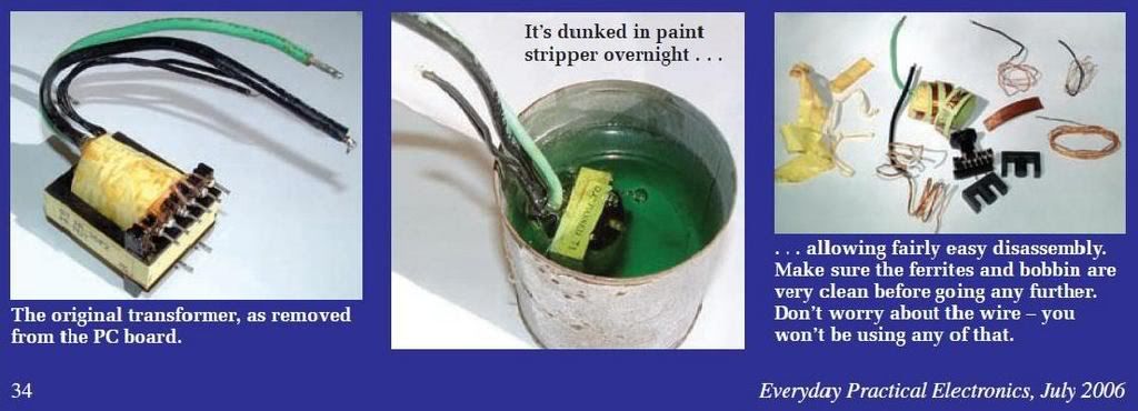
But I did find a way, that I didn't try yet.In EPE(Everyday Practical Electronics)July 2006 on p.34 they say:"The original transformer,as removed from the PC board.It's dunked in the paint stripper overnight...allowing fairly easy disassembly."
What do you think, will it work allright?
But I did find a way, that I didn't try yet.In EPE(Everyday Practical Electronics)July 2006 on p.34 they say:"The original transformer,as removed from the PC board.It's dunked in the paint stripper overnight...allowing fairly easy disassembly."
What do you think, will it work allright?
Paint stripper
Luka
I have read where paint stripper's have been used but beware it is a caustic chemical and the directions for use should be followed to the letter and it will give mixed results. I only mention the microwave for I have one in the lab. I use the small PC cores for gate drive transformers as well as inductors for prototype's.
chas1
- Home
- Amplifiers
- Power Supplies
- Offline full-bridge SMPS… need help