http://server6.theimagehosting.com/image.php?img=smps_full_bridge.JPG
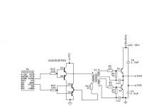
This is my smps who works in full-bridge mode, but I have some questions about it. Is this chematic works ? end How many power i have ? I need about 500w. My ETD49 is 3F3 material who has 400mT induction so I wind about 16 turns in primary. TR1 end TR3 are small ferrite toroids. I need to know all errors of this shematic, because i wan't to blow my details and my self...
This is my smps who works in full-bridge mode, but I have some questions about it. Is this chematic works ? end How many power i have ? I need about 500w. My ETD49 is 3F3 material who has 400mT induction so I wind about 16 turns in primary. TR1 end TR3 are small ferrite toroids. I need to know all errors of this shematic, because i wan't to blow my details and my self...
I'm already smelling the smoke after taking a look at that schematic. Check other threads in order to learn how to implement proper gate drive.
Full Bridge
I have referred members of this forum to this site numerous times because it has an example of a fullbridge design with all construction details and it also has a parts source included along with PCB layouts. If you need help with fullbridge topology check it out. Look for the K6 amplifier on this site there you will find all the pdf files for this project. It uses the ETD49 core set.
chas1
http://www.a-and-t-labs.com/
try this post for gate drive.......
http://www.diyaudio.com/forums/showthread.php?postid=1041829#post1041829
jimbo
http://www.diyaudio.com/forums/showthread.php?postid=1041829#post1041829
jimbo
So I have tried to take the transformer apart.Well all I have to say is the it is the safest and fastest way if you put it in boiling water.After 7-8 min core came off like it was only standing on.This method I would recommend to any of you, that have to do the same thing.
Zuijkis said:http://server6.theimagehosting.com/image.php?img=smps_full_bridge.JPG
This is my smps who works in full-bridge mode, but I have some questions about it. Is this chematic works ? end How many power i have ? I need about 500w. My ETD49 is 3F3 material who has 400mT induction so I wind about 16 turns in primary. TR1 end TR3 are small ferrite toroids. I need to know all errors of this shematic, because i wan't to blow my details and my self...
Eva said:I'm already smelling the smoke after taking a look at that schematic. Check other threads in order to learn how to implement proper gate drive.
Eva,
What kind of smoke?
 The type from cross-conducting MOSFETS across a 330VDC Rail, or the kind of the core reaching saturation at 400mT? 😉
I repaint the schematic.
http://server6.theimagehosting.com/image.php?img=smps_full_bridge.06e.JPG
I used this http://www.a-and-t-labs.com/K6_Sw_Amp/art_schematic/k6pwr.pdf like sample. 🙄
http://server6.theimagehosting.com/image.php?img=smps_full_bridge.06e.JPG
I used this http://www.a-and-t-labs.com/K6_Sw_Amp/art_schematic/k6pwr.pdf like sample. 🙄
Zuijkis
If you have not committed to pcb for your supply and you only need about 500 watts then I would forget a fullbridge and go with halfbridge or two switch forward converter, fewer parts and less of a headache. If you review this thread you will find the answer's to many of your questions including schematic's of gate drive circuits and even complete schematics of halfbridge supplies.
But if you want to design your own gate drive this might help since you are using a small toroid. I am also including a schematic of a gate drive circuit I used.
Example:
fsw = 50kHz
VCC = 12VDC
I use the Ferroxcube 846T250-3C8 ( small toroid)
Al = 1650 mH / 1000T
Lets start with a 14 turn primary:
The inductance would be Lp = Al x N^2 = (14/1000)^2 x 1650mH = 323uH
aprox primary current:
12V X 10uS/323uH = 370mA (drive exceeds SG3525 spec's) want this around 100mA, we need to add turns or increase fsw!!
Lets try 20 turns now we have 660uH and 181ma (still the current is high and the leakage inductance will be high and could effect the operation of the circuit)This could be fixed by Schottky diodes from ground to OutA and OutB of Sg3525.
If we stay with 50kHz fsw then for fewer primary turns we need to buffer the SG3525 with a simple buffer of some type, I used the circuit in the schematic below.
Now we can use about 14T in the primary and 12 turns in each secondary. The secondary side will require a small resistor in series with the gate and should be bypassed by an RC filter and for added protection a zener diode from gate to source. This design should be verified with a scope between gate and source of the devices you are going to use with only VCC applied to the SG3525 and no bulk supply applied to the circuit. You should see nice sharp pulses with very little tilt on the tops, if not check your filter , all connections, OUTA and OUTB of SG3525, output of emitter follower and use the back of Finger on components for touch test.
All components should be cool to the touch if not , scope test should uncover problem.
Remember to apply insulation between windings to isolate the high and low side secondarys from the primary.
I recycled a small E-core transformer from a PC supply for my gate drive for ease of isolation works fine. The calculations are the same for the main transformer.
repeated here:
12E8/(4 x fsw x Bmax X Ae) = number primary turns. For 1:1 secondary turns will be same. You will have to check with scope and rewind as necessary (DIY fun)
You can drive small transformers using the totem pole outputs of the SG3525 without coupling cap in primary because the drive is balanced and during the Toff the primary is grounded and there are no transients to turn on the mosfet's.
I think we would all be better served if we see some one struggling in the water to provide them with some sort of life vest or rope rather than to say your are drowning and supplying the formula for H^2^O or how many mLiters of water it takes to drown.
If someone tells you the water is deep and you can't swim only foolish people would jump in.
chas1
Attachments
Gate-Drive Tutorial
Chas-
Thanks for the good tutorial. I saved it as a Word file and filed it in my SMPS- Tutorials section. Nice-n-concise, to-the-point method of doing it. I, too, have a number of old proportional base-driver xfmrs from AT & ATX supplies, and this will help me in the conversion of them to MOSFET Gate drive. 😎
If I do need to buffer, I have chosen MJE172 & -182 for my buffer drivers.
Steve
Driver's
N-Channel
Thanks for reply ,yes your choice of transistors will make a more robust buffer and since I have this pair I will use them in finished design for I used the motorola mpsa56 and mpsa42 in my breadboard design.
chas1
N-Channel
Thanks for reply ,yes your choice of transistors will make a more robust buffer and since I have this pair I will use them in finished design for I used the motorola mpsa56 and mpsa42 in my breadboard design.
chas1
Driver IC's
I am sure driver IC's should work well for the applications they are designed for and if you follow the suggestions in the application notes you shouldn't experience any problems. The only gotcha I have heard about is layout of pcb they are picky and the other downer for DIY is cost and support circuits and pcb space. I can drive a bridge with one transformer at a cost of less than a dollar. The only way to go IMHO.
chas1
trafo assembly
How do you get ride of low freq. buzz from trafo? In PC supply the trafo is coated with epoxy.Since this way is not the cheapest thing, although it works best, but what to use instead?
How do you get ride of low freq. buzz from trafo? In PC supply the trafo is coated with epoxy.Since this way is not the cheapest thing, although it works best, but what to use instead?
Noise in xfmr's
Most transformer noise is caused by mechanical coupling. Before reassembling a PC Xfmr make sure all surfaces are clean of all old varnish, then check the mechanical fit and the core set mates on all surfaces. The difficult part is the center leg , to check that it is mating properly use some powder or crayon and color the square surface of the center leg and pull it together with a small tie wrap, remove the tie wrap and check for an even pattern of coloration on the mating surface. After you have proved your transformer you should use a varnish or clear finger nail polish to assure that all surfaces are in contact and will remain that way thru assembly and normal use.
chas1
Core fits together great, but there is only insulating tape to hold it together.I don't think I can do much better job than it does now, and that is not perfect.Core can move pretty much while on bobbin.What can I do?
I ask this because I have rewinded trafo from PC supply for output of 13.5v at 230w.I used the 5v track and its components like diodes.It works now but I have to get bigger caps for the output filter.
I ask this because I have rewinded trafo from PC supply for output of 13.5v at 230w.I used the 5v track and its components like diodes.It works now but I have to get bigger caps for the output filter.
xfmr problems
I don't understand, if you used the orginal bobbin and core set for your xfmr there should be no play the only thing is to make sure the core set is firmly attached. I have used 3m tape to hold mine together during testing and had very good results. The ATX power supply has a 12 volt output that can easily be converted to 14 volts @ 8 Amps. If noise is still present check out your design with a scope the problem could be elsewhere.
chas1
Yes everything is original,but there is still 0.5mm or less space between the bobbin and core if that is even the problem, but I didn't use 3m of tape that is for sure.Maybe winds are not tighten enought?
Yes ATX can put easylly 14v@8Amps, but it can't do that @17Amps, that is why I used 5v rail that is now 14v.
Should I use glue to keep core in one piece?
It produces low freq. buzz only when there is no or small load,when pulses are narrow.It gets better with higher load.
Yes ATX can put easylly 14v@8Amps, but it can't do that @17Amps, that is why I used 5v rail that is now 14v.
Should I use glue to keep core in one piece?
It produces low freq. buzz only when there is no or small load,when pulses are narrow.It gets better with higher load.
Smps using monitor power ic
hi everybody,
Im trying to use monitor ic (DP104c) found on samsung monitors, for making an smps foa amplifier. It supports only flyback configuration. How much power can we really reliably obtain from a flyback configuration? I had tried a 200w amplifier and it worked quite fine. Waiting for replies...
Hi rejithcv,
Flyback is good for about 100w, or is it more?.(http://schmidt-walter.fbe.fh-darmstadt.de/smps_e/smps_e.html)
I have tried again but this time with 2x1000uF and 2x output coils as two low pass filters in series(before only one coil and 10uF cap ).The buzz has gone away, and I get a 12.5v no mather what the load is.So now I will have to get a zener to get it to 13.5v, wich I cant whit this resistor net-divider.
Flyback is good for about 100w, or is it more?.(http://schmidt-walter.fbe.fh-darmstadt.de/smps_e/smps_e.html)
I have tried again but this time with 2x1000uF and 2x output coils as two low pass filters in series(before only one coil and 10uF cap
).The buzz has gone away, and I get a 12.5v no mather what the load is.So now I will have to get a zener to get it to 13.5v, wich I cant whit this resistor net-divider.Noise in xfmr's
Luka
Glad to see you on top of problem with your supply, A difficult part of design is the compensation in the feedback loop. If not done properly you will have all types of problems. Remeber you changed the output requirements from 5 Volts to 12 volts @ 15A therefore the feedback compensation has to be changed for your new requirements.
The output filter resonant frequency changes along with the gain and phase when you add or change the values of these components, therefore the compensation must be changed.
chas1
- Home
- Amplifiers
- Power Supplies
- Offline full-bridge SMPS… need help