sivan_and said:I think therz some error around the pin8 of IC 101
SoftStart capacitor C120 -ve end should be at ground pot pin12 of IC U101;
Yes U are right the capacitor should be connected to GND of the circuit instead of the Vref/2 way on the eror amp's + input. Thank you for your correction.
Output Inductor values
Hi every body
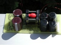
I pulled the (Driving transformer version or anyway) circuit from my amplifier(240W+120+120W RMS) and looked to inductors. They are wound 22sp with 2*0.8 cu wires and the value of the inductors 22uH.
The circuit supplies my amplifier without any doubt
Please look the last 3 replies written by me.
Regards
Hi every body
I pulled the (Driving transformer version or anyway) circuit from my amplifier(240W+120+120W RMS) and looked to inductors. They are wound 22sp with 2*0.8 cu wires and the value of the inductors 22uH.
The circuit supplies my amplifier without any doubt
Please look the last 3 replies written by me.
Regards
Hi,
Here is the half of the shematic. I draw it on multisim and therefore could not get place all the shematic in one file but will enclose the left side of the circuit. In fact it is same as IR2113 version's eror section and I think only the inputfilter section left.
Regards
Here is the half of the shematic. I draw it on multisim and therefore could not get place all the shematic in one file but will enclose the left side of the circuit. In fact it is same as IR2113 version's eror section and I think only the inputfilter section left.
Regards
Attachments
Whortless said:Hi,
Here is the half of the shematic. I draw it on multisim and therefore could not get place all the shematic in one file but will enclose the left side of the circuit. In fact it is same as IR2113 version's eror section and I think only the inputfilter section left.
Regards
Whats the purpose of 2N2907 ?
medogrizli said:
Whats the purpose of 2N2907 ?
it is for fast shut down the mosfets.
medogrizli wrote:
therz no need the zener diode will clamp the negative excursions of the driver transformer.Whats the purpose of 2N2907
Finally working
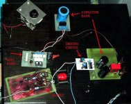
Yes it is complited and working on 230AC 😀. First test was with variable resistor.Because of heat generated on it , it was driven for only few seconds.Heat dissapated for that time was 145W .
.
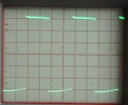
Wave forms are nice squers as they should be.
Yes it is complited and working on 230AC 😀. First test was with variable resistor.Because of heat generated on it , it was driven for only few seconds.Heat dissapated for that time was 145W
.Wave forms are nice squers as they should be.
Re: Finally working
post schematics😀
luka said:Yes it is complited and working on 230AC 😀. First test was with variable resistor.Because of heat generated on it , it was driven for only few seconds.Heat dissapated for that time was 145W
Wave forms are nice squers as they should be.
post schematics😀
O and Whortless, can't wait to see your PCB.It will help me make my PCB smaller then it is now,and everything on one board only.I would like to see the one, where you use IR😀.
Lp, Luka
Lp, Luka
ooops...
I have just fried 4 mosfets (IRF740) in my full bridge powersupply 🙂
The 0.1 R current sense resistors have exploded, and the 20A braker on the house also shut down. 🙂
I measure short circuit on each of the mosfet's legs, but (i'm surprised) the IR2113s seem to be OK.
I don't have idea, whay these FETs have died...
Maybe, the spike on the leading edge on the transformer's primary was tooooo high.
If there's interest, I can post a schematic.
- Home
- Amplifiers
- Power Supplies
- Offline full-bridge SMPS… need help