Shouldn't there be a CL60 from the power supply to ground, or am I misremembering? (or not seeing it here)
I will have to pull the top off of mine.
Russellc
That is also my understanding Russell
But I will change it to the way Zen Mod suggested and report back on the results after testing
However I can see in my mechanical engineering minds eye - that Zen Mods suggestion wil give the safety earth an unrestricted direct path and the chassis and the audio ground is still protected by the CL60
But as a mechanically minded person - I could be wrong
Thats why I'm asking for knowledge based input from more savvy people on the forum
plenty of pictures here : Papa’s Koan (M)2 , an amp for living room | Zen Mod Blog
Dead as Dodo without signal , alive as ZM with signal

Dead as Dodo without signal , alive as ZM with signal
Even Pa did it..... Look here
http://www.6moons.com/audioreviews/firstwatt11/open1_big.jpg
And mine also needed some steel around the transformer.
ZM build solution is very clever giving some shielding for free!
http://www.6moons.com/audioreviews/firstwatt11/open1_big.jpg
And mine also needed some steel around the transformer.
ZM build solution is very clever giving some shielding for free!
Thank you gentlemen
Before I proceed - I have a couple of questions for Zen Mod
My M2 has 2 CL60s
One is at the safety earth ( as per drawing ) And the other is on the live wire at the On / Off switch at the front of the amp
So in light of the extra info regarding the CL60
Q - Do I still remove the CL 60 completely from the safety earth position or leave it as is
Q - I see your square PCB transformer covers in your build photos
Can I use double sided adhesive copper shielding tape ? As I have some on hand
I can also make a square can cover out of alloy plate - is alloy suitable to use for this purpose
And is that yellow wire soldered from the square transformer shield cover to an earth point
Here is an earlier photo I took of the CL60 connected on the live power side
Attachments
I already wrote clearly what goes in what hierarchy ....... and you can clearly see in my blog how I made it
and , again , (mains) NTC is going to be hot - supported only with wires ( no pcb or other proper mechanical way ) - that's recipe for disaster
so - put it either on terminal block or on dedicated pcb , with proper spacers form case itself
regarding input xformer shielding - that's more cosmetic than anything else - you need proper steel cage for them ......... to prevent /decrease magnetic garbage around them
copper is good as RF shield , not magnetic one
Last edited:
Just for the record, the 6moons photo shows the thermistor which is in
series with the AC line. There is another one hidden which connects signal
ground to chassis/earth.
Credit for that invention goes to one of the technicians at Adcom years
ago - I am sorry that I have forgotten his name.
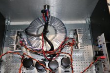
In that photo you can also see the Mu-metal shields I made for the Edcor
transformers. I found I didn't need them for the Jensen transformers, but it
is also important to keep them as far from the power transformer as
possible and rotate the toroid for least noise on both channels with the
RCA input connections attached to a source.
series with the AC line. There is another one hidden which connects signal
ground to chassis/earth.
Credit for that invention goes to one of the technicians at Adcom years
ago - I am sorry that I have forgotten his name.
In that photo you can also see the Mu-metal shields I made for the Edcor
transformers. I found I didn't need them for the Jensen transformers, but it
is also important to keep them as far from the power transformer as
possible and rotate the toroid for least noise on both channels with the
RCA input connections attached to a source.
Copper worked OK in mine - see post #1279. I don't have any hum. I did enclose the power transformer with a stainless steel pot, though.I already wrote clearly what goes in what hierarchy ....... and you can clearly see in my blog how I made it
and , again , (mains) NTC is going to be hot - supported only with wires ( no pcb or other proper mechanical way ) - that's recipe for disaster
so - put it either on terminal block or on dedicated pcb , with proper spacers form case itself
regarding input xformer shielding - that's more cosmetic than anything else - you need proper steel cage for them ......... to prevent /decrease magnetic garbage around them
copper is good as RF shield , not magnetic one
Just for the record, the 6moons photo shows the thermistor which is in
series with the AC line. There is another one hidden which connects signal
ground to chassis/earth.
Credit for that invention goes to one of the technicians at Adcom years
ago - I am sorry that I have forgotten his name.
In that photo you can also see the Mu-metal shields I made for the Edcor
transformers. I found I didn't need them for the Jensen transformers, but it
is also important to keep them as far from the power transformer as
possible and rotate the toroid for least noise on both channels with the
RCA input connections attached to a source.
Thanks for the input Mr Pass
I'm sure that my mate and fellow builder in my M2 would have spotted that and used the same idea
Copper worked OK in mine - see post #1279. I don't have any hum. I did enclose the power transformer with a stainless steel pot, though.
It seems that the consensus is -- shield the torodial and the Edcor's and use a shielded power supply cable
I now have the shielded power supply cable ready to go
The filtered IEC is arriving on Monday so these 2 items will be fitted first
As a mechanical engineer I can fassion a full box enclosure for the Edcore's so I purchased a sheet of Mumetal and is in transit as I post
Then I will either make or purchase a Torodial cover if required after the other items are fitted
Will keep you in the loop with photos as components are installed
Again thank you for the input gentlemen - it's much appreciated
Last edited:
ham can is good for toroidal , if you have it around
take care to avoid shortie between xfornmer bolt , cover and case
take care to avoid shortie between xfornmer bolt , cover and case
I bought 2 pcs of this item, 15cm diameter should be enough for FW donut. For me it's not too expensive instead of DIY version canned steel which might not look good 😀
Audio DIY needed Metal Shield plate cover for toroid transformer with many size
Once I had also planned to 'steal' my wife cooking pan but would need extra hard work
Audio DIY needed Metal Shield plate cover for toroid transformer with many size
Once I had also planned to 'steal' my wife cooking pan but would need extra hard work
I have searched for a suitable Torodial transformer cover to purchase, however they are all to small
The requirement for my M2 build is 155mm Dia approx 6" X 60mm H
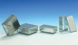
So I searched the house with my wife, then we remembered on festive occasions we often purchase biscuits / cookies - sometimes sweets that are packaged in a lovely round tins
We found these 2 in the back of the cupboard
The one on the right is a better height but both are a perfect diameter
The good thing about this type of tin is that it's lid clicks on / off, and because the wire loom is on top of the Torodial I can cut away and bend a small section of the lid to accomodate the wiring without to much trouble
It's also possible to line the inside of the tin with copper tape for extra shielding
A spray paint of your preferred colour and it's perfect for those larger 6" torodial's
I'm not sure if festive packaging of sweets and biscuits come in smaller sized tins but it's worth a look
Anyway I thought to post up my find as a tip for other members to try out 😎😎😎
The requirement for my M2 build is 155mm Dia approx 6" X 60mm H
So I searched the house with my wife, then we remembered on festive occasions we often purchase biscuits / cookies - sometimes sweets that are packaged in a lovely round tins
We found these 2 in the back of the cupboard
The one on the right is a better height but both are a perfect diameter
The good thing about this type of tin is that it's lid clicks on / off, and because the wire loom is on top of the Torodial I can cut away and bend a small section of the lid to accomodate the wiring without to much trouble
It's also possible to line the inside of the tin with copper tape for extra shielding
A spray paint of your preferred colour and it's perfect for those larger 6" torodial's
I'm not sure if festive packaging of sweets and biscuits come in smaller sized tins but it's worth a look
Anyway I thought to post up my find as a tip for other members to try out 😎😎😎
Attachments

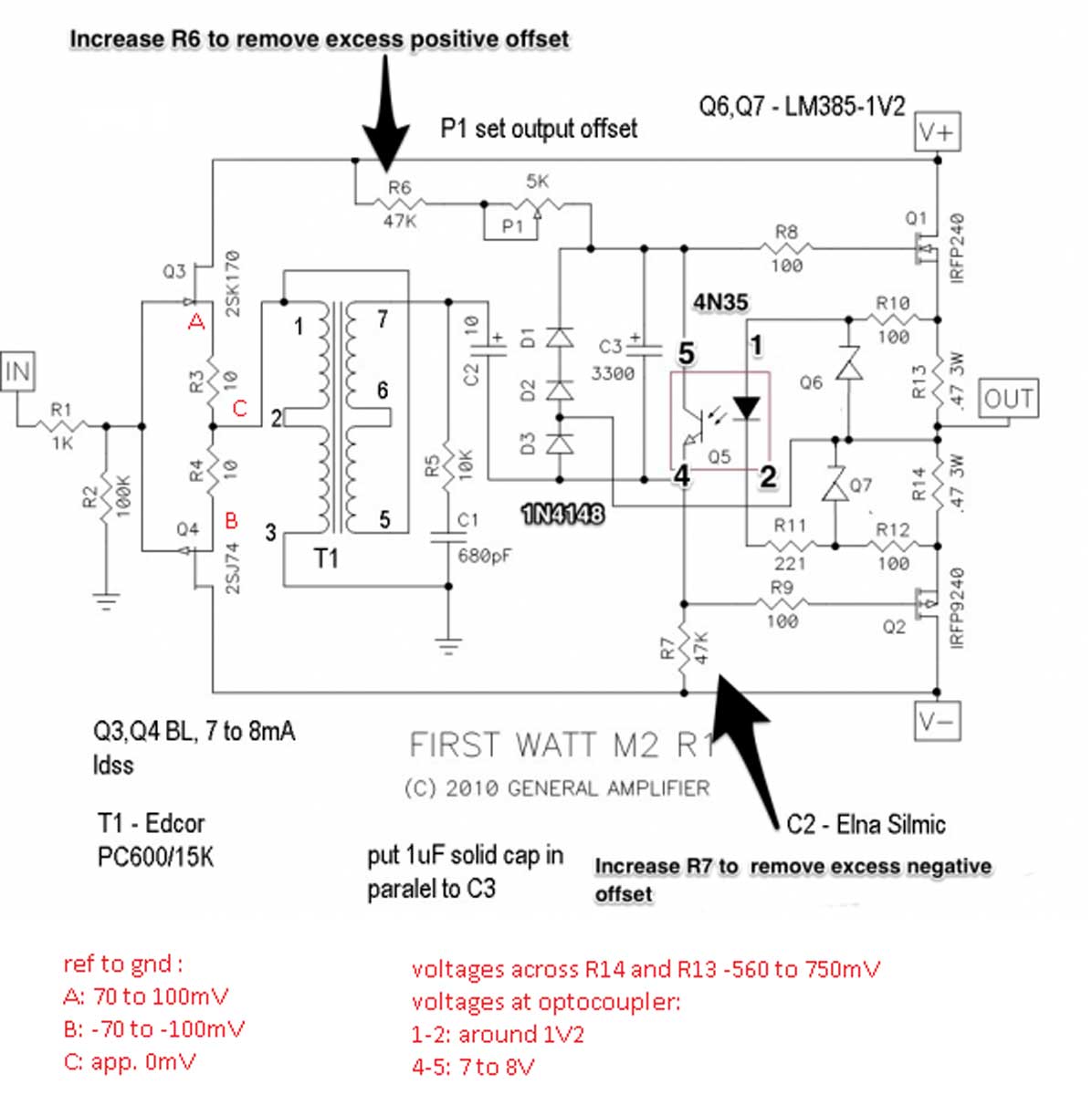
A, B and C read ok on the newly built board. Across R13 and R14 ok, pins 1-2 ok and pin 4-5 a little high at 9.4v.
I get low volume music behind a heavy hum in that channel, the hum stays even when the input wiring is removed, volume has no impact on hum level with input wire connected. Any ideas?
Last edited:
pins 4-5 at 9 volts is ok. depends on the Fets. The important figure is
the voltage across the .47 ohm resistors, which is the bias current.
the voltage across the .47 ohm resistors, which is the bias current.
- Home
- Amplifiers
- Pass Labs
- Official M2 schematic