Hi Russelc,
I'm in the same boat as you. I built the AlephJ before the F6, but didn't have the heart to pull the boards because it sounded so nice, so I built a new chassis and PSU for my F6. The F6 became my favorite. Now I have the M6 boards stuffed and complete so I'm thinking about pulling the Aleph boards, a nice cheap way to hear the M2.
Paul
How do you compare F-6 and Aleph J? M-2 is well worth hearing!
Russellc
Pro-blem
I managed to get everything hooked up with 44V across +/- and the offset zeroed by changing R7 to 49.9k. But it won't play any magical sounds out of either side.😕
These are Buzz's old M2 PCB's.
What points should I measure to see where the problem is?
I managed to get everything hooked up with 44V across +/- and the offset zeroed by changing R7 to 49.9k. But it won't play any magical sounds out of either side.😕
These are Buzz's old M2 PCB's.
What points should I measure to see where the problem is?
Attachments
What points should I measure to see where the problem is?
what is your voltage across C3?
I managed to get everything hooked up with 44V across +/- and the offset zeroed by changing R7 to 49.9k. But it won't play any magical sounds out of either side.😕
These are Buzz's old M2 PCB's.
What points should I measure to see where the problem is?
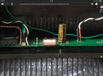
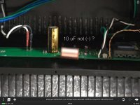
Check polarity (-) (+ ) of 10 uF little electrochemicals all is ok ?
Best regards 🙂
Last edited:
just re-read my post with exact resistors nomenclature :
so - R13,R14 to 0R33
R11 to zero ; ignore previous post where I typed 100R , referencing R11 original value - that was brainfart or typo , whatever
Hey Zen Mod, I'm using Toshiba 2SK1530/2SJ201 as well. Is this bias tweak to get the Toshiba's to a more optimal operating point and to coax a bit more current drive, since these are lower transconductance parts than Fairchild and IRF parts?
Thinking about putting 1R3 parallel with 0R47 and 10R parallel with 221R so as to compare the two Iq's.....hmm
Cinco
I managed to get everything hooked up with 44V across +/- and the offset zeroed by changing R7 to 49.9k. But it won't play any magical sounds out of either side.😕
These are Buzz's old M2 PCB's.
What points should I measure to see where the problem is?
I would PM buzz....I suppose your heatsinks are warming up and you are getting proper measurement across source resistors? Or no?
Russellc

I managed to get everything hooked up with 44V across +/- and the offset zeroed by changing R7 to 49.9k. But it won't play any magical sounds out of either side.😕
These are Buzz's old M2 PCB's.
What points should I measure to see where the problem is?
When Justin put his boards up for sale he mentioned an error which requires wrapping the source resistor around the soldered leg of the MOSFET. Did you do that?
http://www.diyaudio.com/forums/swap-meet/282086-pass-m2-clone.html#post4507731
Source resistors are warmed up and sitting at 0.63vdc
C2 measures 333. mvdc
Both C2 capacitors are connected so + is to transformer, same as in schematic.
22V + and - testing to board ground.
C3 is 10V
Grinberg,
Yes I did fangdangle the one board to match the schematic. basically swap the grid and source on the one IRFP FET
C2 measures 333. mvdc
Both C2 capacitors are connected so + is to transformer, same as in schematic.
22V + and - testing to board ground.
C3 is 10V
Grinberg,
Yes I did fangdangle the one board to match the schematic. basically swap the grid and source on the one IRFP FET
Last edited:
Hey Zen Mod, I'm using Toshiba 2SK1530/2SJ201 as well. Is this bias tweak to get the Toshiba's to a more optimal operating point and to coax a bit more current drive, since these are lower transconductance parts than Fairchild and IRF parts?
Thinking about putting 1R3 parallel with 0R47 and 10R parallel with 221R so as to compare the two Iq's.....hmm
Cinco
yup ,that was an idea to let Toshibas breathe easier
Looks like both transformers are broken🙁
pin1 to ground = no connection. It should be 230r or so.
Thanks for everyones help. 🙂
pin1 to ground = no connection. It should be 230r or so.
Thanks for everyones help. 🙂
Looks like both transformers are broken🙁
pin1 to ground = no connection. It should be 230r or so.
Thanks for everyones help. 🙂
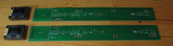
The transformer's wiring on Buzzforb's PCBs does not match the published schematic. He swapped pins 1 and 3, 7 and 5.
If you are wondering how do I know that, the answer is: I have an unused pair of his boards.
Attachments
Last edited:
so - is it pcb , or damaged xformers ?
I would triple check xformers , carefully referring datasheet
I would triple check xformers , carefully referring datasheet
stop confusing us 
check xformers per datasheet
desolder them from pcb (carefully!!) if needed
or wait for confirmation from anyone who already made it with same pcbs
check xformers per datasheet
desolder them from pcb (carefully!!) if needed
or wait for confirmation from anyone who already made it with same pcbs
I was confused first. 🙂
after soldering little hair strand on the output winding of transformers magical sound is now playing.
It might be a good idea to drop a little crazy glue on these little wires where they attach to the post to keep them stable.
after soldering little hair strand on the output winding of transformers magical sound is now playing.
It might be a good idea to drop a little crazy glue on these little wires where they attach to the post to keep them stable.
....after soldering little hair strand on the output winding of transformers magical sound is now playing.
Congratulations Damuffin

Hi Russell,
The alephj is very nice, I preferred it over the F5, but I also preferred the F6 over the Aleph J on my system. The bass is very good on the F6. I'm using a tube pre (Aikido) with it, a very nice combo. I tried several SS Preamps but the Aikido is hard to beat.
Paul
The alephj is very nice, I preferred it over the F5, but I also preferred the F6 over the Aleph J on my system. The bass is very good on the F6. I'm using a tube pre (Aikido) with it, a very nice combo. I tried several SS Preamps but the Aikido is hard to beat.
Paul
- Home
- Amplifiers
- Pass Labs
- Official M2 schematic