It is difficult for me to comment, as I have very very good relationship with Jan.
Dear Pavel. Please feel free to comment all you want 😉
Bo;
I'm glad to hear that you are back on track 😉
All;
As I have stated many times in emails and on internet forums, the LYNX was from the very beginning ment as a "replacement" Amp for the good old 70-80s very dynamic Studio Power Amps.
Quite a lot have over the years asked for the LYNX to have "supernatural" specs like BW up to 1 MHz etc., which I always has dissuaded. Please tread the design for what it is; A replacement clone for the 30-40 years old Amps.
The original LYNX was from the very beginning fitted with the LF356 opamp, which works great in this design. This opamp is a bit slow and noisy for todays standard, but it was the standard opamp many years back.......
Over the past years, many have build the LYNX (either using original or home made PCBs) with succes, even though I never thought that the LYNX would be so popular in the DIY world as it has become.
Also the LYNX may be quite a big mouthful for some first time diy'ers due to the high power involved.
And last. Thanks to all who participate in this thread, as it is impossible for me to get time to reply to every question asked 😉
I'll drink to that!!ACD said:Also the LYNX may be quite a big mouthful for some first time diy'ers due to the high power involved.

Even though I had a big setback I really enjoy this diy-experience. I would also like to state that if I had followed the QAG to the point, it would never have happened.
Thanks all for the help!
Best regards,
/Bo
Don't be sure 😉 But it would have saved you some £$€I would also like to state that if I had followed the QAG to the point, it would never have happened.
Playing around with +/-40 to 60VDC/800W can cause much damage. One little mistake when fitting the components and then

BV:
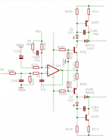
Interesting! You have introduced three more components, R1=100R, R3=? and C4=47pF. What is the value of R3?
Best regards,
/Bo
Interesting! You have introduced three more components, R1=100R, R3=? and C4=47pF. What is the value of R3?
Best regards,
/Bo
BV, what´s the purpose of Led D1 and D2 ?
And which type?
The IC is twisted upside down on your schematic, but the numbering of the bones is ok.
regards
And which type?
The IC is twisted upside down on your schematic, but the numbering of the bones is ok.
regards
Ragnwald said:
The IC is twisted upside down on your schematic,
regards
What??
PMA said:
What??
He he, +up and -down.
On Lynxschematic +down and -up.
But the numberings is ok.
I could really use some help here. I thought everything was ok, but as I slowly raised the bias go get 1.4V tpA-tpC the 0.5A fuse blew. I bought new ones, but the -DC fuse blows immediately. It turns out that Q111 was blown, measuring short between all three pins BCE.
I switched the Q111 (MJE15033) and put in another fuse. This time everyting was ok and I measured 124V over the rails.
Then I was going to measure tpA-tpC again, but as soon as I touched tpC with the scope-probe GND-clamp, the fuse blew and the Q111 is also blown again.
The scope is on safety shield (ground) and so is the GND connection on the amp.
What could be wrong?? Help!
Best regards,
/Bo
Forget it.
I just realized I learned lesson one from the oscilloscope school. Be careful with the ground loops.
Shorting -DC was not the healthiest thing for Q111.
Best regards,
/Bo
I just realized I learned lesson one from the oscilloscope school. Be careful with the ground loops.
Shorting -DC was not the healthiest thing for Q111.
Best regards,
/Bo
To avoid saturation Q101, Q102 at overdrive. In originall schematic diodes D107,D108 are practically without function, bypased with conductive C-B junctions Q101, Q102 at overdrive. Led´s are ordinary small red diodes.BV, what´s the purpose of Led D1 and D2 ?
I have now built the replacement card for the one that went into flames. The base resistors burst so bad that the conductive paths on the card were burnt off.
If there is anyone out there with extra 15032/3, some 2W 33R resistors and 8 2.2R base resistors for sale, please let me know.
Best regards,
/Bo
If there is anyone out there with extra 15032/3, some 2W 33R resistors and 8 2.2R base resistors for sale, please let me know.
Best regards,
/Bo
Yesterday I tried the OPA827 from TI, but oscillations reappeared. I really have to learn how to tune these bastards.
Is there any good documentation online on bandwidth limiting etc?
I bought P-A's adapters from svalander.se and soldered the surface mount OP onto those, together with the 100nF caps. The other caps were the original ones though, 100pF and 2 x 33pF.
I'm awaiting my OPA627's. If those work I will not touch a thing...
Also: Thank you Jan for helping me out, component-wise!
Best regards,
/Bo
It is a feedback issue; you must be able to understand and investigate loop gain; stability margin and phase margin. Your problem is a fast opamp plus slow output power stage. As far as you have slow opamp (741), you are stable.
For OPA827, use the recommendation by BV, shown previously.
For OPA827, use the recommendation by BV, shown previously.
One of my card is up and running, but the other all of a sudden has started to draw some power on the input side. 0.5A fast fuses as well as 1A fast fuses blow on the +DC side. Everything seems to be ok when measuring the trasistors etc. Anyone has any tips on what could be the problem?
Best regards,
/Bo
Best regards,
/Bo
This really puzzles me. If someone can explain, I'd be grateful.
It seems, if I connect power to the output stage, but leave the fuseholders empty, the input stage draws a lot of power. Is this true, and if so, why? Looking at the schematic, I can see no way of current flowing from the input +DC and -DC through to GND on the output stage.
My working card did the same (input stage fuses blew), but when I added the fuses, it worked fine again.
Best regards,
/Bo
- Status
- Not open for further replies.
- Home
- Amplifiers
- Solid State
- Official LYNX Power Amp builder’s thread