You have a simple three-stage amplifier with direct CE-CK-CE coupling. The quiescent current (bias) is set at 4.7 ohms and 56k.
Try to remove 15k (GNFB). Check the health of the transistors (replace). Looks like a faulty output transistor.
OldDIY, I've check all six (both channels) transistors, they're good.
Oh yes, I have.
This amp was part of a Voice of Music reel to reel model 744 with lid speakers.
One of their premium models.
It was tongue in cheek 😉
Never heard of them though
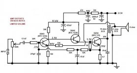
We have your schematic. To debug remotely without endless guessing, the dc operating points of all 3 transistors will give something concrete and simple for us to work with. Please post voltages at E, B, and C for all 3 transistors. Annotate on schematic if possible. This will guide the next step of the diagnosis or get us quickly to the actual problem.
The high gain and distortion both point to the feedback resistor being open or the ring value. It would be odd for this to occur on both channels.
It’s been pointed out before, but are you just expecting too much from this simple amp???
What is your signal source, modern equip has higher signal levels than what this amp may have been designed for.
Vbe1=0,32v Vbe2=0.8v ?
Check your reading. Voltages seem to be reasonable.
I can, however, not understand why any wise old
technician would not have a scope etc readily available.
He may be expecting more from us than from himself ?
We have your schematic. To debug remotely without endless guessing, the dc operating points of all 3 transistors will give something concrete and simple for us to work with. Please post voltages at E, B, and C for all 3 transistors. Annotate on schematic if possible. This will guide the next step of the diagnosis or get us quickly to the actual problem.
The high gain and distortion both point to the feedback resistor being open or the ring value. It would be odd for this to occur on both channels.
It’s been pointed out before, but are you just expecting too much from this simple amp???
What is your signal source, modern equip has higher signal levels than what this amp may have been designed for.
I'm using a CD player connected to an attenuator, resulting in 150mv output.
Check your reading. Voltages seem to be reasonable.
I can, however, not understand why any wise old
technician would not have a scope etc readily available.
He may be expecting more from us than from himself ?
I haven't brought down the scope or my sig gen yet because this little amp is someone's who asked me to go over it.
I've so far replaced the caps and a couple resistors out of tolerance.
You only need 20-50 mv 🙁
Low frequencies, as used to, will not be. The voltage gain is 150 and the output voltage is less than 3V.
Low frequencies, as used to, will not be. The voltage gain is 150 and the output voltage is less than 3V.
Last edited:
Based on the biasing presented, the biasing looks correct for the design, and the transistors do not look to be malfunctioning. Vbe3 may appear a bit low due to heating as it’s dissipating several watts.
Based on the biasing presented, the biasing looks correct for the design, and the transistors do not look to be malfunctioning. Vbe3 may appear a bit low due to heating as it’s dissipating several watts.
Yes, thanks.
The TO66 output transistors get only moderately warm at idle, both channels are on the same large-enough heatsink. (w/mica/grease)
Also, their tops are in contact with the bottom of the (aluminum) chassis with mica/grease to aid in cooling.
When I get back to the bench, I'll rig up the o'scope and sig gen and hopefully post some scope pics.
I didn't want to get this deeply involved, lord knows I've serviced thousands of amps in the shop, but this weird one is luring and bugging me.
I've got other projects going on as well.
As a side note, with about 180mV audio going in, I'm getting about 1.8V out to speaker before clipping/distortion.
Last edited:
If you’re measuring 1.8 volts on a DMM that’s about all you’re going to get. It can only do 1.5 watts, based on voltage and Q point, assuming the transformer is optimal at 100 to 150 ohms primary. If you’re getting 0.4 watts average with music before it goes to hell you’re doing good.
Is that pp, rms, or peak for the units?
If you put a 33 ohm load on it, does the peak output voltage increase?
I'll check that out when I'm back on the bench. 😉
Ok, I´ll waste some time on this hopeless project.
1) voltages measured look acceptable, considering the quickie way they were taken.
I expect around 0.6 to 065V at each Vbe junction.
Since measurements were not taken across them but relative to a third point (in this case ground) small errors add up.
Vbe @:
Q1: 0.68V --- perfect
Q2: 0.8V ---- reasonable given it´s an indirect result
Q3: 0.54V ---- again an indirect measurement and in general power transistors show less, closer to 0.5V to 0.55V so again check.
Q3 idle current: 0.76V/4.7 ohm=0.16A
Confirmed by voltage drop across OT primary: (21.5-20)V/10 ohm DCR=0.15A
Q3 dissipation: 19V*0.15A=2.85W , round it up to 3W.
OT primary impedance for maximum power: 20 Vpk/0.15 Apk= 133 ohm (so wgkski was real accurate)
Possible RMS power and substracting, say, 2V transistor saturation: (18*0.15)W/2=1.35W RMS
That, with everything properly matched and working "perfect", I would be happy with about 1W RMS.
Given the intended application, driving a 3 x 5" speaker (resonance 150-180-200Hz) mounted on a tape recorder lid,transfomer must be sized for a lower cutoff frequency of about 200Hz, so do not even DREAM of asking any lower frequency out of it.
Speaker probably has a 14 or 16mm voice coil, single piece thin paper cone, tiny weak Alnic magnet, so do not expect much from it.
It will be reasonably/usably efficient at voice frequencies (50 to 2500Hz), nothing below, reaching above whatever chance may give it.
Measure power at edge of clipping (which will be harsh) at 440 or 1kHz which are in its passband.
https://www.mediacollege.com/audio/tone/files/440Hz_44100Hz_16bit_30sec.mp3
https://www.mediacollege.com/audio/tone/files/1kHz_44100Hz_16bit_30sec.mp3
If no Lab present, play 440Hz tone which sounds like a flute through any MP3 player, including Phone (set to repeat or repeat 1 so you get a continuous tone) and slowly rise level until it gets reedy/buzzy, then lower a little.
You will find by ear the start of clipping point quite accurately, this is what I do when I am outside my home/lab or on Tour with a band at a Hotel room or at a School or Church, when I want to test something "bare handed".
Calculate real power and post results.
Ok guys..
I scoped the speaker outputs with a 1kHz sine wave, driving both my bench test speakers (ported 8 ohm 6.5" + tweeter)
I got a pretty darn clean wave of 1.8V PP just before clipping.
I suppose that's all it's gonna do, I was just hoping that I could muster an extra watt or two per/ch out of the thing, which is what the owner asked me to pull out of the rabbit's hat.
- Home
- Amplifiers
- Solid State
- Odd amp issues - Experts Needed