Was the input transistor replaced previously? The new part would probably have a much higher beta,
which could upset the operation of the DC bias network. The output transistor would then have
too little bias current. Try increasing the 56k resistor to compensate.
which could upset the operation of the DC bias network. The output transistor would then have
too little bias current. Try increasing the 56k resistor to compensate.
Last edited:
Hi rayma.
The transistors all look original, (factory soldering) and test fine.
But I replaced the 470uF cap that was missing, and wondering is it was intensionally left out.
It just distorts, like it's got too much gain when the volume is increased, yet plays clearly at low volume.
The transistors all look original, (factory soldering) and test fine.
But I replaced the 470uF cap that was missing, and wondering is it was intensionally left out.
It just distorts, like it's got too much gain when the volume is increased, yet plays clearly at low volume.
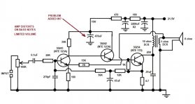
In this current assembly, the voltage gain is R (FB) 15K / 100, resulting in 150.
That's a lot for such a small power device.
Perhaps dividing the value of R (FB) by 2 would decrease the distortion while leaving enough gain to the device?
It's easy to test without soldering, just by touching with a second resistor in parallel to R (FB).
That's a lot for such a small power device.
Perhaps dividing the value of R (FB) by 2 would decrease the distortion while leaving enough gain to the device?
It's easy to test without soldering, just by touching with a second resistor in parallel to R (FB).
If you have a 'scope and sig gen, feed it a sine wave and see where the distortion occurs as you crank it up (try at different freqs too)
Has the speaker (assuming its a complete amp and speaker combo) been replaced for something incorrect... or perhaps just an incorrect speaker being hung on the output if it is a stand alone amp.
If you have a 'scope and sig gen, feed it a sine wave and see where the distortion occurs as you crank it up (try at different freqs too)
Got them, yes.
Haven't pulled them down from the shelf yet.
Has the speaker (assuming its a complete amp and speaker combo) been replaced for something incorrect... or perhaps just an incorrect speaker being hung on the output if it is a stand alone amp.
I'm using my bench test speakers, 8 ohm 6.5 inch woofer plus tweeter bookshelf type.
The originals are 8 ohm 5x7 alnico ovals.
I'm wondering that since I replaced the missing 470uF cap, while stabilizing the B+ feed to the 1st (30243) transistor, is it affecting degeneration to the 2nd (30242) acting as a darlington for the output.
Note the 470 ohm feed to both of these transistors.
Also, the output is a TO66 on a heatsink capable of 3A rated 300V. (RCA #30254)
This is a stereo pair BTW.
Last edited:
Amplifier SE klass A with a power of less than 1 W with a sensitivity of about 20 mV for AM radio.
The sensitivity can be reduced by reducing the FB resistor to 1k5. The question is whether stability will continue?
Or increase the 22k resistor at the input to 220k.
The sensitivity can be reduced by reducing the FB resistor to 1k5. The question is whether stability will continue?
Or increase the 22k resistor at the input to 220k.
Last edited:
Maybe the 47 or 470 uF are a bit leaky, upsetting the output stage bias current. You could measure the impedance of the transformer from the turns ratio squared, to get an idea of what bias current would be correct on that 21.5 volt supply. Knowing what the current is supposed to be compared to what it is might give you a clue as to what has drifted. Too high and you saturate the trafo, and that would result in distorted bass. Too low and just no power. Just no power also results in distorted bass. Maybe the trafo just got itself magnetized somehow (perhaps a speaker magnet got stuck to it once) and that’s causing the distortion even with the correct bias.
Maybe the 47 or 470 uF are a bit leaky, upsetting the output stage bias current. You could measure the impedance of the transformer from the turns ratio squared, to get an idea of what bias current would be correct on that 21.5 volt supply. Knowing what the current is supposed to be compared to what it is might give you a clue as to what has drifted. Too high and you saturate the trafo, and that would result in distorted bass. Too low and just no power. Just no power also results in distorted bass. Maybe the trafo just got itself magnetized somehow (perhaps a speaker magnet got stuck to it once) and that’s causing the distortion even with the correct bias.
Both the 47uF's are new replacements.
The 470uF was missing from the board, I don't know if/what the original value was, or if it was left out intentionally, so I just used a 470uF.
By the way, that 470uF/470 ohm B+ feed is common to both channels.
Distortion is identical on both channels.
Last edited:
The drop across the DCR suggests 150 mA of bias current. Is the output transistor heat sinked for 3.2 watts? If not, it could be running high. It would also suggest only 1.5 watts output power, into 133 ohms. Is the trafo primary impedance in that ballpark? (Put in 1 volt RMS in the secondary, measure primary volts, calculate Z).
You joking, huh?.... distorts if cranked particularly on bass.
Any experts see an issue with the diagram?.... changes needed to cure distortion?
Only slightly better than "amplifiers" posted by a Forum Member I won´t name 🙄 , complaining about exact same problems .... I wonder why. 😛
DIY Transistor D718 Amplifier Circuit 12V with Volume Control || Powefull Bass - YouTube
EDIT:
NOW, if you don´t mind rubbing shoulders with NASA 😱, you can use some of their ADVANCED Techniques 😎
Yup, I mean using ........ INTEGRATED Circuits 😱
here, this guy is a GENIUS.
He knows you don´t really need to reach the Moon, only some sub orbital flight is fine, so he removes some of those unnecessary IC pins.
(between you and me, they are there only to impress feeble minded people, not really needed)
Enjoy:
DIY Powerful Ultra Bass Amplifier TDA7297, Simple circuit diagram - YouTube
Last edited:
I changed the 470uF cap to 2200 @ 25V - no change.
The B+ no signal at the cap is 19V, which drops to 17V and lower once distortion kicks in.
Connecting a common 8 ohm 5x7 oval speaker still doesn't give good results, because at about 25% (9 0'clock position) of the volume pot it still distorts. (using a line level source)
I tacked a 1.8K resistor across the 15K - much lower volume predictably, but still distorts at the same 25% of volume control.
This is a commercial product, not home brew, so it seems to me this thing should perform better.
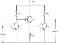
A similar design online of a 3 stage DC coupled amp uses a PNP driving the output (see pic)
So I wonder why the amp I have uses an NPN there.
The B+ no signal at the cap is 19V, which drops to 17V and lower once distortion kicks in.
Connecting a common 8 ohm 5x7 oval speaker still doesn't give good results, because at about 25% (9 0'clock position) of the volume pot it still distorts. (using a line level source)
I tacked a 1.8K resistor across the 15K - much lower volume predictably, but still distorts at the same 25% of volume control.
This is a commercial product, not home brew, so it seems to me this thing should perform better.
A similar design online of a 3 stage DC coupled amp uses a PNP driving the output (see pic)
So I wonder why the amp I have uses an NPN there.
Attachments
Both channels being the same has to be a clue... are you certain the speakers aren't at the root of this... I know I asked and you answered 🙂 but maybe it is meant to drive something of higher impedance that 8 ohm.
Apart from the supply there is nothing else common to both.
Apart from the supply there is nothing else common to both.
This is a commercial product, not home brew, so it seems to me this thing should perform better.
😀😀😀😀
You've obviously not seen many commercial products 🙂
There's a lot of utter crud out there
You have a simple three-stage amplifier with direct CE-CK-CE coupling. The quiescent current (bias) is set at 4.7 ohms and 56k.
Try to remove 15k (GNFB). Check the health of the transistors (replace). Looks like a faulty output transistor.
Try to remove 15k (GNFB). Check the health of the transistors (replace). Looks like a faulty output transistor.
Last edited:
Both channels being the same has to be a clue... are you certain the speakers aren't at the root of this... I know I asked and you answered 🙂 but maybe it is meant to drive something of higher impedance that 8 ohm.
Apart from the supply there is nothing else common to both.
I have the original speakers that came factory with the unit, 8 ohm 5x7 with alnico magnets circa 1967.
😀😀😀😀
You've obviously not seen many commercial products 🙂
There's a lot of utter crud out there
Oh yes, I have.
This amp was part of a Voice of Music reel to reel model 744 with lid speakers.
One of their premium models.
- Home
- Amplifiers
- Solid State
- Odd amp issues - Experts Needed