Hello,
I've read many things about ODAC, I've build O2 and I like very much.
But if this is a DIY forum I'd like to have more info about ODAC like schematic and so on.
At the moment for me ODAC is only a commercial product like many others.
I think that I'll buy one but is like to buy a Iphone in a shopping centre.
Ciao
Guglielmo
Italy
Hi,
I have received a note from GFEC and they are agreeable with my releasing the schematic. Once the ODAC cards are available and shipping I will make the schematic available on my site.
I will not make the schematic available sooner as we need to make sure the layout and parts choices made during the prototype phase work properly during manufacturing.
Regards,
George Boudreau
Yoyodyne Consulting
Ok perfect.
At the moment I'm using ES9023 build on a proto board connected to SDTrans in sincronous mode with I2s and MCLk and in the future I'd like to tweak your board if possible to use in the same way and compare USB with SD card reader.
Ciao
Guglielmo
At the moment I'm using ES9023 build on a proto board connected to SDTrans in sincronous mode with I2s and MCLk and in the future I'd like to tweak your board if possible to use in the same way and compare USB with SD card reader.
Ciao
Guglielmo
Does ESS Tech discourage the posting of schematics with their stuff? I assume not, but they also are very restrictive with their technology.
I understand why the datasheets don't get posted, but why not schematics? What's GFEC afraid of?
I understand why the datasheets don't get posted, but why not schematics? What's GFEC afraid of?
ESS Technology datasheets are readily available from their distributors, you only have to ask. Just don't ask me for them.
GFEC requires a multi-page, non-disclosure agreement be signed before you can receive any datasheets for their Tenor products. Since I had to sign this agreement to receive the information needed, including programming tools, I felt it wise to ask GFEC it is was acceptable to release the schematic.
NOTE: The programming tools are still restricted and cannot be released.
Generally you will not find schematics of commercial products published so as to keep designs from being cloned. Once the ODAC schematics, with component values, are published it will be easy to duplicate (off shore)
The 'secret' to the ODAC's performance is in the layout and choice of components. NwAvGuy spent hours upon hours tweaking component choices. To achieve the datasheet performance specifications is quite an achievement. To do so with a USB bus powered device with a restrictive footprint is remarkable. The devil is in the details and having the proper testing equipment.
George Boudreau
Yoyodyne Consulting
Coolbeans.
I'm certain that once this thing starts getting copied by the Asia-shotgun-suppliers they're going to switch to the TE8802L, add a seperate clock and rework the thing into some frankenDAC that nobody recognizes... and it won't measure nearly as well either.
Hey... any thought of having a version with the GFEC and ESS components prepopulated and programmed, and the rest of the stuff in a kit for us to try our hand at SMD soldering? I'm sure we're a year away from that (if it ever happens), but I can dream, can't I?
The only thing the TE8802L will bring to the table is extended sample rates. Since the DAC is working at spec there is no room for 'improvement'.
If you want to burn your fingers on SMD and DAC's you can look at the open source audio-widget USB5102. Plenty of chippy things and little parts you can lose as you populate the board. The USB8741, base on the WM8741, is still a few weeks away but will have enough parts to keep any solder sniffer happy.
Regards,
George Boudreau
Yoyodyne Consulting
My current DAC/Amp uses the same USB interface as the ODAC, so maybe I'm just looking for different. It is cool that the TE8802L can be programmed to UAC1 and also includes 88.2kHz. So far, I've only seen two people in all the various forums who have requested the 88.2kHz functionality.
I don't care. What I am stewing about though is what enclosure to use and how to best mount it. I think I'll be using mounting pegs from the bottom since I can't seem to find anything that is dimensionally perfect for a slide-in.
I don't care. What I am stewing about though is what enclosure to use and how to best mount it. I think I'll be using mounting pegs from the bottom since I can't seem to find anything that is dimensionally perfect for a slide-in.
Hi, pretty stalled here.... maybe we can get some discusions going now, George posted the [URL="http://www.yoyodyneconsulting.ca/pages/ODAC.html]schematics on his webpage[/URL], have fun analyzing 😉
Stefan
Stefan
Got my Odac in from JDS labs today...
Had a bit of a hard time installing it, it was actually easy, but there was no instructions and very little to no info online on how to get it up and runing. Im posting this to help others.. Basically
1. Do not remove battery terminals, I desoldered mine, then realized they are supposed to stay.
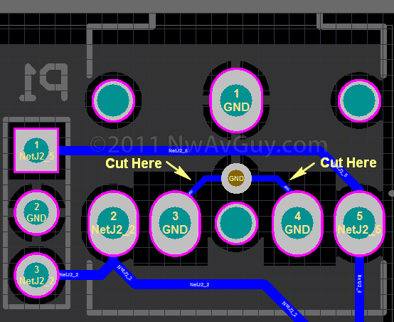
2. Cut 2 traces under PCB:
3. Solder Wires, from LR Line out on the Odac to P1 input on O2. Left is first hole closest to PCB, Middle is Ground, 3rd hole is right channel. I just "bridged" the 2 ground solder connections on the Odac and ran a single wire from there to the middle P2 hole.
4. use nut/bolt or, do what I did, a small piece of foam tape works perfectly, securely fashions the PCB, and is the perfect gap and lines up perfectly with the side grooves in the case.
5. re-assemble case and your done.
Had a bit of a hard time installing it, it was actually easy, but there was no instructions and very little to no info online on how to get it up and runing. Im posting this to help others.. Basically
1. Do not remove battery terminals, I desoldered mine, then realized they are supposed to stay.
2. Cut 2 traces under PCB:
3. Solder Wires, from LR Line out on the Odac to P1 input on O2. Left is first hole closest to PCB, Middle is Ground, 3rd hole is right channel. I just "bridged" the 2 ground solder connections on the Odac and ran a single wire from there to the middle P2 hole.
4. use nut/bolt or, do what I did, a small piece of foam tape works perfectly, securely fashions the PCB, and is the perfect gap and lines up perfectly with the side grooves in the case.
5. re-assemble case and your done.
Is there a part number for the output jack for the ODAC listed anywhere? I suspect it is the same as the O2, but I haven't seen it specified.
Thanks for your time.
-Aaron.
Thanks for your time.
-Aaron.
Is there a part number for the output jack for the ODAC listed anywhere? I suspect it is the same as the O2, but I haven't seen it specified.
Thanks for your time.
-Aaron.
Hi Aaron
3.5mm Digikey CP-3523SJCT-ND
I will list them in my shop shortly as well. I also give them away as freebee wirh every ODAC 😉
Stefan
Hi Aaron
3.5mm Digikey CP-3523SJCT-ND
I will list them in my shop shortly as well. I also give them away as freebee wirh every ODAC 😉
Stefan
Thank you so much!
-Aaron.
oh boy... this is a big one.
I had Foobar set to 24bit output Wasapi (Odac). But windows audio control panel was set to 16 bit 44.1, I noticed that windows volume control was still controlling Foobar even though it's set to wasapi. This is odd behavior, but more importantly it means that it's still going though the windows stack, which means that foobar's 24 bit output was getting resampled to 16 bit by the windows driver. I changed the windows options to 24-bit 44.1 and holy cow, what a difference, sounds like a whole new level of greatness.
anyway, long story short, make sure Foobar and Windows audio settings are aligned, and why does it not bypass the windows audio completely? (Wasapi)
this is with windows 7 64 bit. Foobar defaults to 24 bit, windows defaults to 16 bit, this IS IMPORTANT. big difference in sound quality.
Last edited:
I have not spent much time trying to, to be honest, I was just surprised, as I have several other USB audio type devices and Dacs, USB SPDIF converters etc, and the windows volume control never works when they are set to WASAPI in Foobar. Im not sure it matters much, as long as they are aligned there should not be any resampling up/down etc by windows.
Recieved my ODAC today. I must praise swalter for nice packaging and all communication.
This little thing is a beast. Beated my Audio-GD DAC easily. Much more air between instruments, very nice spatial information, more refined and natural sound.
This little thing is a beast. Beated my Audio-GD DAC easily. Much more air between instruments, very nice spatial information, more refined and natural sound.
- Status
- Not open for further replies.
- Home
- More Vendors...
- Head 'n' HiFi - Walter
- ODAC - general and technical discussions