Yeah, I understand your concern with the efficiency, it's a balance walk, but if you don't hear anything it migh not be any issue in your design...
In general I think you can easily check with a 2ch scope the same time you feed your amplifier with a 20 kHz sine, preferably a burst signal.. (this is probably the highest frequency we have to cope with, maybe a bit more if your customers use vinyl as vinyls can go even higher in frequency than CD's, all deppending on what people feed their amplifiers with..), then you can tailor the rise and fall time empirically so you always have a minimum margin to the lower rail voltage without getting into clipping at the lower rail voltage.
But of course we should not forget to keep an eye on the switching FET so it doesn't start to burn because of switching losses inside it.
At how many volts from the lower rail voltage does the FET switch in the higher rail voltage?
Cheers Michael
The Switched elevation from lower to upper rail voltage is 45V....First Tier at +- 45V and Second Tier at +-90V....
Ok, but that's the rail voltages, but respect to the output signal when do you switch in the upper rails voltae, that was my question, eg. if lower rail is 45 volt then you switch in 90 volt when the output reach perhaps 42 volt, right?
You know that the miller capacitor grows extremely much the last volts so why switching in exactely at 45 volts, besides if you switch in at a lower voltage you don't need that gate diode and can keep much softer switching without the risk the output FET's would run into clipping.
Cheers Michael
You know that the miller capacitor grows extremely much the last volts so why switching in exactely at 45 volts, besides if you switch in at a lower voltage you don't need that gate diode and can keep much softer switching without the risk the output FET's would run into clipping.
Cheers Michael
Ok I get it you were asking about the margin left between when the FET switches....then its about 5 volts....The FET switches to upper rail when the peak output voltage reaches 40V.....
Acc to me slow switching leads to higher dissipation in linear region curve of FET...Correct me If i am wrong....
K a n w a r
Acc to me slow switching leads to higher dissipation in linear region curve of FET...Correct me If i am wrong....
K a n w a r
Hi Kanwar,
sorry for my delay, bussy weekend.
Yes you are absolutely right, the slower you switch on/off the switching FET the more switching losses you will see.
But you shouldn't focus too much on that, it's still small comparing to OPT losses due to slow transients in the bass region, you still will have considerable gains with the Class-H topology.
Don't forget if you have an army OPT FET's you have a very large Miller capacitance, IF the switch FET have a very fast dv/dt you can encounter AMPERES of gate drive current during the switch time, do your drivers manage that? (eg. which mean the output signal will jerk every time you switch between lower and higher rail despite of the FB.)
Hope that helped! 🙂
Cheers Michael
Class H rail switching
Hi,
can I presume that part of the design problem is switching between rails while maintaining a continuous supply without the rails shorting together. A similar problem to cross conduction in a conventional push pull amplifier where matching the speed between the upper and lower halves both in the off direction and in the on direction.
Presumably there are solutions that work well and some that don't.
Re: Class H rail switching
Definately Michael,
High dV/dT rate will result in higher gate current demand...my TLP250 drivers could source/Sink 2 amperes of gate current...
I have slowed the Switching speed and updated the schematic....increased the marginal headroom voltage to 8 volts from 5 volts also....spikes are very much lowered....
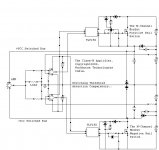
No Andrew , its insnot cross conduction, but it appears more like a Seamless transfer between 2 Tiers through a Switch which is a mosfet and the supplies cannot cross-conduct because there is always a Series Commutation diode present in between them....
regards,
K a n w a r
Ultima Thule said:Hi Kanwar,
sorry for my delay, bussy weekend.
Yes you are absolutely right, the slower you switch on/off the switching FET the more switching losses you will see.
But you shouldn't focus too much on that, it's still small comparing to OPT losses due to slow transients in the bass region, you still will have considerable gains with the Class-H topology.
Don't forget if you have an army OPT FET's you have a very large Miller capacitance, IF the switch FET have a very fast dv/dt you can encounter AMPERES of gate drive current during the switch time, do your drivers manage that? (eg. which mean the output signal will jerk every time you switch between lower and higher rail despite of the FB.)
Hope that helped! 🙂
Cheers Michael
Definately Michael,
High dV/dT rate will result in higher gate current demand...my TLP250 drivers could source/Sink 2 amperes of gate current...
I have slowed the Switching speed and updated the schematic....increased the marginal headroom voltage to 8 volts from 5 volts also....spikes are very much lowered....
AndrewT said:Hi,
can I presume that part of the design problem is switching between rails while maintaining a continuous supply without the rails shorting together. A similar problem to cross conduction in a conventional push pull amplifier where matching the speed between the upper and lower halves both in the off direction and in the on direction.
Presumably there are solutions that work well and some that don't.
No Andrew , its insnot cross conduction, but it appears more like a Seamless transfer between 2 Tiers through a Switch which is a mosfet and the supplies cannot cross-conduct because there is always a Series Commutation diode present in between them....
regards,
K a n w a r
Attachments
Hi Andrew,
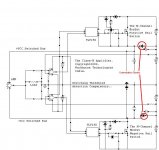
This is the diode which helps the current from lower Tier to transfer or commute to the Switched bus of amplifier when the upper Tier is Switch is OPEN not in conduction mode.....
regards,
K a n wa r
This is the diode which helps the current from lower Tier to transfer or commute to the Switched bus of amplifier when the upper Tier is Switch is OPEN not in conduction mode.....
regards,
K a n wa r
Hi,
is the
is the
the diode beside the RC next to the lower voltage supply?Series Commutation diode
Re: Re: Class H rail switching
Kanwar,
good to hear it developes well!
Just a clarification to my previous post, what I meant was not the switching FET, but your output FET's in your audio amplifier when I wrote OPT.
The input capacitance in your switching FET is small in comparisson with your OPT's in the amp section, it's here you will encounter big gate current durig the switching time all dependent on the dv/dt. But the softer you drive your switching FET the smaller the gate current in your OPT amp section.
Cheers Michael
Workhorse said:
Definately Michael,
High dV/dT rate will result in higher gate current demand...my TLP250 drivers could source/Sink 2 amperes of gate current...
I have slowed the Switching speed and updated the schematic....increased the marginal headroom voltage to 8 volts from 5 volts also....spikes are very much lowered....
regards,
K a n w a r
Kanwar,
good to hear it developes well!
Just a clarification to my previous post, what I meant was not the switching FET, but your output FET's in your audio amplifier when I wrote OPT.
The input capacitance in your switching FET is small in comparisson with your OPT's in the amp section, it's here you will encounter big gate current durig the switching time all dependent on the dv/dt. But the softer you drive your switching FET the smaller the gate current in your OPT amp section.
Cheers Michael
Re: Re: Re: Class H rail switching
Hi Michael,
Thanks for clarifying the information.....The gate drivers of output transistors are PushPull types BD140/139 therefore peak current of 1A is obtained easily...I have already soften the switching of Tiers....
Cheers,
K a n w a r
Ultima Thule said:
Kanwar,
good to hear it developes well!
Just a clarification to my previous post, what I meant was not the switching FET, but your output FET's in your audio amplifier when I wrote OPT.
The input capacitance in your switching FET is small in comparisson with your OPT's in the amp section, it's here you will encounter big gate current during the switching time all dependent on the dv/dt. But the softer you drive your switching FET the smaller the gate current in your OPT amp section.
Cheers Michael
Hi Michael,
Thanks for clarifying the information.....The gate drivers of output transistors are PushPull types BD140/139 therefore peak current of 1A is obtained easily...I have already soften the switching of Tiers....
Cheers,
K a n w a r
Hi Rahul The PCB maker,
What happened to you....no news from you friend...
regards,
K a n w a r
What happened to you....no news from you friend...
regards,
K a n w a r
Sorry Kanwar !
Got the PC set right partialy today only. Had given for an upgrade. Mother board ke LLLL lag gaye.
As for PCB now I am seriously thinking which way to go the L/R sided O/P evices or one sided O/P devices with bias track device in middle.
Kindly advice.
BTW was at Delhi last week bought Build your own HIGH END AUDIO EQUIPMENT from Elektor published by BPB for Rs249/
Realy good stuff covering all its articles as well as PCB layouts.
Will be out of town again for next 3 days but will proceed as per your suggestions.
Regards
Rahul
It can't be so hard to get a computer working. The two that I commonly use are almost made of second hand parts (or third, or fourth 😀 ) that were either discarded by other people or bought at a ridiculous price in some store long after being discontinued. I even got a nice used 19" CRT for little money from some child that was "running out of space in his room" 😀
Also, the inkjet printer that I use to make transparencies costed me nothing. Somebody discarded it because the head positioning mechanism was malfunctioning. Repairing it was just a matter of cleaning some ink and dirt... 🙂
And, well, when budget is short we have emule to cover our software needs 😉
Hi! Eva
Yes it all appers too simple but just do a google on
"no audio device"
And you find what I am talking abt. The whole PC sound system goes crazy there is sure shot cure till date. I just hope you dont have to go thru the same experience. It is amazing to find that the vol control has vanished one fine morning.
As a DIYaudio member and a HAM operator on the other hand it became a nightmare for me. All audio related stuff was simply not working. Format , reinstall all waste the same HDD worked fine on other system, all I can say is maybe my stars were not in too good a configration

Regards
Rahul
Yes it all appers too simple but just do a google on
"no audio device"
And you find what I am talking abt. The whole PC sound system goes crazy there is sure shot cure till date. I just hope you dont have to go thru the same experience. It is amazing to find that the vol control has vanished one fine morning.
As a DIYaudio member and a HAM operator on the other hand it became a nightmare for me. All audio related stuff was simply not working. Format , reinstall all waste the same HDD worked fine on other system, all I can say is maybe my stars were not in too good a configration
Regards
Rahul
Hi Rahul,
L/R orientation would do a symmeric type nicely and could prove better when force cooling is required....do it this way....I wish I could help but busy alot...in daily routines...
regards,
K a n w a r
L/R orientation would do a symmeric type nicely and could prove better when force cooling is required....do it this way....I wish I could help but busy alot...in daily routines...
regards,
K a n w a r
Hi!
OK Kanwar , back now . Thanks for the tip I will get the dimensiones of heatsink available in mkt and position the fets accordingly and proceed.
Will also look at some high end pro amp layouts just to get an idea. This is a new turf for me.
Regards
Rahul
OK Kanwar , back now . Thanks for the tip I will get the dimensiones of heatsink available in mkt and position the fets accordingly and proceed.
Will also look at some high end pro amp layouts just to get an idea. This is a new turf for me.
Regards
Rahul
- Status
- Not open for further replies.
- Home
- Amplifiers
- Solid State
- NVMOS amplifier