For those who want to hard wire the PMD100 in D1V3, here is the circuit diagram.
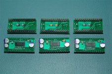
Those who has the converter board:
C1 and C2 are 0.1uF smd MLCC is on the bottom pads.
R1 and LED is on the top. PMD100 is U2 while U1 SM5842 is just a dummy pins.
Assembly sequency:
1. Solder C1, C2 and R1.
2. Solder the two 14 pins strip, align it using a 28 pins IC sockets.
3. Solder the PMD100 IC socket or PMD100 directly on the pcb top.
4. Solder the LED pin socket provided or LED direct on the pcb top.
Enjoy!
Attachments
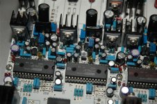
Since PCM1702 output is only +/-1mA max, the IV resistor (R4, R13, R24, & R34) has to be changed to 3k (currently using 2.35k). I did not change the 2700pf silver mica value.
The other change must do is to remove the resistors (R148, R149, R150 & R151). Then the point A voltage will be able to adjust back to 9Vdc. In other words, Q41, Q43, Q45, & Q46 are not required.
The sound of PCM1704 is quite clean and clear a little bit less bass than PCM63. Overall the sound is good and very close to PCM63 sonic. With the cheaper cost of PCM1702U, it is a real bargin to use PCM1702U as replacement.
The next DAC chip can be tried will be PCM1704 or even AD1862 etc... For AD1862, the analogy +/-5V of PCM63 should be changed to +/- 12V.
Have made following changes so far and the sound improve a bit:
1. C4/C15/C25/C36: Use Black Gate Non Polar 10uF 50V E-cap.
2. C24/C35/C223/C229: Change from 1000uf 35V back to 2200uF 16V.
3. R123: 110ohm for XLR digital input; 75 ohm for BNC input; 50ohm for RCA input.
4. C10/C20/C31/C41: Change from Panasonic FC to FM grade; 47uF 25V to 100uF 25V. These capacitors are the analogy supply decoupling just next to the Jfet IV +ve supply. 6x11.2mm
5. C100/C124/C128/C140/C149/C173/C177/C189: Change from Panasonic FC to FM grade; 47uF 25V to 100uF 25V. These capacitors are the analogy supply decoupling capacitors just next to the PCM63 ICs. 6x11.2mm
6. Add a decouple capacitors Panasonic FC 27uF 35 voltage to all 5V regulators ground resistors at R97, R98, R105, R109, R112, R113, R126 & R127 (300 ohm). 5x11.2mm
7. Use PCM63P-K2, Y or KY chips.
Overall, the bass is much deeper and stronger. I try a PCM63KY chip and it really sound better, more harmonics and more musical.
Try some new capacitors and DAC.
1. C4/C15/C25/C36: Black Gate 33uf/16V N.
2. C10/C20/C31/C41: Black Gate FK 100uF 25V
3. C100/C124/C128/C140/C149/C173/C177/C189: Black NX 47u 6.3V.
4. DAC to PCM63P-K2 old parts.
Found the sound is more relax, a bit quieter, better separation of insturment, better sound stage and 3D. Very balance from high to low frequency. K2 is better in sound stage, more extend in high and low freq and better instrument position relative to normal PK version.
Cheers
Attachments
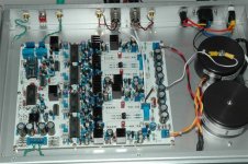
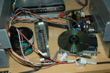
Recently I upgrade my transport from Marantz dvd player to CD-PRO2 with China made controller. Now it is under testing but I find the sound of CD-PRO2 (from SPDIF out) with D1V3 is much better in sound stage, resolution and everything I can hear. The conclusion is that a good CD transport is really better than a normal grade CD transport.
Cheers.
Cheers.
Attachments
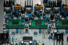
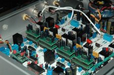
This is another option to use 8 pcs PCM1702U-K (two parallel for each DAC socket so that the output current will be 2mA and no IV resistor/cap need to be modified.
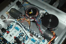
Use all pana FC cap on the analogy supply for decouple of the PCM1702 converter board.
Also you can see the analogy supply is using bigger Panasonic Audio caps. R81/R82 also change to zero ohm wire.
Use all pana FC cap on the analogy supply for decouple of the PCM1702 converter board.
Also you can see the analogy supply is using bigger Panasonic Audio caps. R81/R82 also change to zero ohm wire.
Attachments
Key change from D1V3:
1. Jfet IV: Replace K170 by K369 which has a higher Yfs about 40mS (double of K170). This will also reduce the input impedance of Jfet IV so that the input point will be closer to virtual ground (measured below 20mV for two K369 in parallel at 1FS). Note that K369 is only limited supply (obsloleted also about 10 yrs ago). 8 pcs sorted Idss will be provided.
2. J74 is eliminated due to obsolete.
3. Use K246GR as the current source of LM336 voltage reference.
4. Add 4 jumpers for SM5842 for selection and thus SM5842 output bit can be set from 18 to 24bits. Thus 24-bit DAC like PCM1704 can be used if the converter board fit PCM63 pin assignment.
5. Re-route supply voltage trace using star ground concept to improve background noise.
6. Add a pad for output couple capacitor ¡V 5mm pitch for Muse BP E-cap or Black Gate E-cap.
7. Various change in resistor and capacitor value and size.
8. PCB will be still 2mm thick but use ROHS solder flash for easier soldering.
The above upgrades will reduce the background noise, improve resolution, quieter music background and sound stage will be more focus. Measured distortion is also improve by about 0.01% in balance mode to about 0.048%.
Here is the BOM and Cost of kit, only active, capacitors some ICs are provided and kit will be sold as COMPLETE SET to reduce packing efficiency. Receiver chip, DAC chips and DF parts will not be inclued in the kit. See details attached.
Interested can PM me and I can provide full set of document for review.
Spencer
Interested can PM me and I can provide full set of document for review.
Spencer
Attachments
spencer said:
The above upgrades will reduce the background noise, improve resolution, quieter music background and sound stage will be more focus. Measured distortion is also improve by about 0.01% in balance mode to about 0.048%.
Hi Spencer,
Do you mean 0.0048%, a typo error?
😉
In SE mode, the distortion is about 0.5 to 0.6% at 1FS, 997kHz.
In Balance mode, the distortion is about 0.05% at 1FS, 997kHz.
Major distortion is for 2nd and 3rd harmonics and beyond 3rd harmonic is below -85dB to -90dB.
D1V3 has a little bit higher distortion than D1V33.
Measurement do not really impress anyone!
In Balance mode, the distortion is about 0.05% at 1FS, 997kHz.
Major distortion is for 2nd and 3rd harmonics and beyond 3rd harmonic is below -85dB to -90dB.
D1V3 has a little bit higher distortion than D1V33.
Measurement do not really impress anyone!
OK. I got your meaning.
Measured distortion is also improve by about 0.1% in balance mode to about 0.048%.
Measured distortion is also improve by about 0.1% in balance mode to about 0.048%.
- Home
- Vendor's Bazaar
- NP D1 DAC clone with enhancement