120ohm resistance might be too much for an amp to get into nominal specs (nominal bias current), after power-up.
...
You need one CL-60 in series with the primary winding.
Thanks for pointing that out. Not that I'm particularly keen to substitute the CL-60, but would I not need a higher energy rating given the higher cap bank voltage?
From post #22...
For a "typical" clone of a First Watt power supply, such as Figure 1 of post #17 above, there are a total of eight 15,000uF capacitors, charged to about 24 volts. Note that inrush happens long before the optical bias circuit slooooooowly dials up the bias current and begins to tug down upon the rails.
So the total inrush energy is (1/2) * C * Vsquared = 34.5 Joules. And that's the Joule rating we want in our Inrush Current Limiter device.
The First Watt design for 230VAC mains, uses a single ICL device. So it needs the full 34.5 Joule rating. The circuit option for 115VAC mains uses two ICL devices and each one needs half that rating.
This is one reason why I'm happy with the SL15-60002 ICL. It is rated for 50 Joules. Our dear friend the CL-60 is rated for 36 Joules.
_
From Ametherm's website, I found a close equivalent of the CL-60 but with a higher energy rating of 75J - SL18 10005 (datasheet).
Other specs are: 10 ohm resistance, 5A max steady state current (no minimum listed), and 180C temp. at max current.
As (my usual) luck would have it, it is out of stock everywhere.
I only know that the SE Class A with 2-750 VA Transformers blows each and every time the Main House Fuse, without inrush limiter..(PTC) The Amp usually draws 750Watts / Channel @idle.
In the meantime I have made a LOW CLASS A MODE SELECTOR where the CLASS A runs on 167Watts instead of 750/Channel. But it could be Switched to high mode any time.
Config of the Circuit is parallel to the PTC, a 10 WATT 10 Ohm Resistor, both which will be coupled out when the amp has received it's full voltage, by a Relay. I use two PTC Resistors each of them when Cold =5 ohms & 10 Ampere. The Relay is fed by 12Volts which is regulated after the MAIN RAILS +- which are feeding the Amp itself.
These PTC are in the AC 240 Volts Line. I think to cut off the PTC with a Relay, when the Amp is switched on makes sense because otherwise the PTC getting really hot. In the same time that the PTC is set to off the LINE Of LINE VOLTAGE have =0R or not more than the RELAY contacts itself, so full Voltage (240 Volts) is applied to the Transformers.
And there is no need to have the PTC's hot when not in use.
Last edited:
datasheet[/URL]).
Other specs are: 10 ohm resistance, 5A max steady state current (no minimum listed), and 180C temp. at max current.
As (my usual) luck would have it, it is out of stock everywhere.
Check www.distrelec.ch - but distrelec is acutally from Netherlands.. meaning the supplier, or check Security Check
The ones I use have a common spec to these you want to buy.. I got them very inexpensive from distrelec.ch
The Amp usually draws 750Watts / Channel @idle.
Sorry that's not correct, !
It's 750+ Watts for both channels..
As in my living room the 240 Volts Line voltage variate, it's not always 750Watts, but most times it's above that, and there are days when it's a little bit less.. but for BOTH Channels, sorry for the misinformation respectively wrong information.
@Ground_Point_9, I recommend using the MS22-50004 which is in stock at Newark, Mouser, and DigiKey: octopart link
It's a brutally large device with 230 Joules of inrush energy rating. And they provide lots of good information on the datasheet.
Final steady state "hot" resistance, when running at 2 amps, is 0.79 ohms. However your transformer's final steady state primary current is less than or equal to (300VA / 230V) = 1.5 amps. I'd guess the "hot" resistance would be around 1.6 ohms when operating at 1.5 amperes. So you'll drop 2.4 volts across the ICL. Since 2.4 volts is only 1% of the 230V mains, it seems like an acceptably small voltage loss, at least to me.
Initial "cold" resistance, at 25C before inrush occurs, is 50 ohms. So if your mains inlet + fuse + switch + internal wiring + transformer primary were made of ideal perfect superconductors, with zero point zero milliohms of resistance, peak inrush current will be (230V / (50 + 0.0)) = 4.6 amperes. In the real world, with copper wires, peak current will be less than 4.6 amps.
_
Last edited:
@Ground_Point_9, I recommend using the MS22-50004
...
In the real world, with copper wires, peak current will be less than 4.6 amps.
_
For the recommendation, and the helpful explanation of how to calculate for, and pick the part, many thanks Mark.
I only know that the SE Class A with 2-750 VA Transformers blows each and every time the Main House Fuse, without inrush limiter..(PTC) The Amp usually draws 750Watts / Channel @idle.
In the meantime I have made a LOW CLASS A MODE SELECTOR where the CLASS A runs on 167Watts instead of 750/Channel. But it could be Switched to high mode any time.
Config of the Circuit is parallel to the PTC, a 10 WATT 10 Ohm Resistor, both which will be coupled out when the amp has received it's full voltage, by a Relay. I use two PTC Resistors each of them when Cold =5 ohms & 10 Ampere. The Relay is fed by 12Volts which is regulated after the MAIN RAILS +- which are feeding the Amp itself.
These PTC are in the AC 240 Volts Line. I think to cut off the PTC with a Relay, when the Amp is switched on makes sense because otherwise the PTC getting really hot. In the same time that the PTC is set to off the LINE Of LINE VOLTAGE have =0R or not more than the RELAY contacts itself, so full Voltage (240 Volts) is applied to the Transformers.
And there is no need to have the PTC's hot when not in use.
Sorry Guys, today it's not my day..
this should read NTC - was in a hurry.. This would be proper
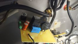
Also I have two versions, on with 24Volts on the regulator for the Relay and one for 12 Volts.
The 24 volt works better.. With the 12 Version I had to change the relay several times already. But I think it's a problem for the Quality of the relay..
In the pic you can see the actual one.. the Parallel resistor is mounted near the Fuse Socket, not on this board.
Attachments
@Ground_Point_9, I recommend using the MS22-50004 which is in stock at Newark, Mouser, and DigiKey: octopart link
It's a brutally large device with 230 Joules of inrush energy rating. And they provide lots of good information on the datasheet.
Final steady state "hot" resistance, when running at 2 amps, is 0.79 ohms. However your transformer's final steady state primary current is less than or equal to (300VA / 230V) = 1.5 amps. I'd guess the "hot" resistance would be around 1.6 ohms when operating at 1.5 amperes. So you'll drop 2.4 volts across the ICL. Since 2.4 volts is only 1% of the 230V mains, it seems like an acceptably small voltage loss, at least to me.
Initial "cold" resistance, at 25C before inrush occurs, is 50 ohms. So if your mains inlet + fuse + switch + internal wiring + transformer primary were made of ideal perfect superconductors, with zero point zero milliohms of resistance, peak inrush current will be (230V / (50 + 0.0)) = 4.6 amperes. In the real world, with copper wires, peak current will be less than 4.6 amps.
_
I was always calculating the hot resistance & current based on actual amplifier current consumption:
My Aleph J draws a 4A constant current at 2 X 24.5V (my rails are sitting between 24 - 25V loaded). So we arrive at 196W.
Ignoring the transformer losses, this real-life consumption translates to 196W / 240V = "only" 0.82A. This is the "hot" current that runs through the thermistor, which is perfect for CL-60 rating, ensuring very low hot resistance.
I'd assume that F4 runs at lesser Iq, which means even lesser hot current than 0.8A...
Assuming that F4 draws 3A (1.5A per AMP PCB), 24V DC rails when loaded, and 220V AC, we get:
144W of total power draw.
144 / 220 = only 0.65A of hot current, which is less than half of what you calculated by taking the nominal VA transformer rating, and not the actual amp power draw.
Last edited:
This thread got me to do some calculations & I thought I'd share.
FW clone of F1J, 18,000uF x4 PSU caps per channel, 24V rail = 20.7 joules of inrush energy per mains thermistor (two parallel 115V primaries, each with a CL-60).
FW clone of F3, 15,000uF x4 PSU caps per channel, 46V rail = 63.5 joules of inrush energy per mains thermistor.
Aleph 30 clone, 22000uF x4 PSU caps per channel, 41.4V rail (+/- 20.7V) = 75.5 joules of inrush energy per mains thermistor.
I've been using CL-60's in all of these applications (max 36 joules energy rated). Something to think about.
Thank you Mark Johnson for the informative post #22 on this thread:
For a 8 x 22,000 uF capacitors at ~+/-24v rails the Joule rating required would be 1/2 * 176,000 * 24^2 = 50.69
The SL15-60002 is rated at 50 Joules; using one SL15-60002 for the power supply running on a 230V AC line voltage - would that be too tight or just doable? Would it be better to consider 2 x SL15-60002 in series?
And with reference to post # 65 from MJ:
If the transformer is rated at 400VA, then is it correct to calculate that the AC voltage drop will be ~2.76V with a single SL15-60002, and ~3.7V with 2 of them in series?
The power supply schematic is attached for reference(First Watt F6 Power Supply).
For a "typical" clone of a First Watt power supply, such as Figure 1 of post #17 above, there are a total of eight 15,000uF capacitors, charged to about 24 volts. Note that inrush happens long before the optical bias circuit slooooooowly dials up the bias current and begins to tug down upon the rails.
So the total inrush energy is (1/2) * C * Vsquared = 34.5 Joules. And that's the Joule rating we want in our Inrush Current Limiter device.
The First Watt design for 230VAC mains, uses a single ICL device. So it needs the full 34.5 Joule rating. The circuit option for 115VAC mains uses...
So the total inrush energy is (1/2) * C * Vsquared = 34.5 Joules. And that's the Joule rating we want in our Inrush Current Limiter device.
The First Watt design for 230VAC mains, uses a single ICL device. So it needs the full 34.5 Joule rating. The circuit option for 115VAC mains uses...

For a 8 x 22,000 uF capacitors at ~+/-24v rails the Joule rating required would be 1/2 * 176,000 * 24^2 = 50.69
The SL15-60002 is rated at 50 Joules; using one SL15-60002 for the power supply running on a 230V AC line voltage - would that be too tight or just doable? Would it be better to consider 2 x SL15-60002 in series?
And with reference to post # 65 from MJ:
@Ground_Point_9, I recommend using the MS22-50004 which is in stock at Newark, Mouser, and DigiKey: octopart link
It's a brutally large device with 230 Joules of inrush energy rating. And they provide lots of good information on the datasheet.
Final steady state "hot" resistance, when running at 2 amps, is 0.79 ohms. However your transformer's final steady state primary current is less than or equal to (300VA / 230V) = 1.5 amps. I'd guess the "hot" resistance would be around 1.6 ohms when operating at 1.5 amperes. So you'll drop 2.4 volts across the ICL. Since 2.4 volts...
If the transformer is rated at 400VA, then is it correct to calculate that the AC voltage drop will be ~2.76V with a single SL15-60002, and ~3.7V with 2 of them in series?
The power supply schematic is attached for reference(First Watt F6 Power Supply).
Attachments
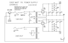
The asymptotic AC voltage drop across the Inrush Current Limiter (at t=infinity after turn-on) will be different for 115VAC mains than for 230VAC mains. I cannot find a place in your post where you mention the mains voltage.
Mark,
Sorry for the confusion - I had mentioned in line 3 of my post - it is 230V AC mains:

And if concerned with the Joule rating, I should have been thinking 2 SL15-60002 in parallel and not in series...
Sorry for the confusion - I had mentioned in line 3 of my post - it is 230V AC mains:
And if concerned with the Joule rating, I should have been thinking 2 SL15-60002 in parallel and not in series...
If you increase the total capacitance by a factor of (22000 / 15000) then you need to increase the Joule rating by the same factor: 1.47X .
As your arithmetic indicates, 34.5 Joules (before) x 1.47 = 50.7 Joules (after)
It's appropriate that when you move up to Big Boy capacitors, you also move up to Big Boy inrush current limiter discs. You will pay a little more money in exchange for a lot more Joule rating. A 50 Joule inrush current limiter disc is insufficient for Big Boys.
Your steady state current requirement is less than or equal to (400 VA / 230 Volts) = 1.74 amperes. Probably less since it's unlikely you'd run the transformer at 100% of its max VA rating continuously ("steady state"). But conservative design practices demand that your equipment must survive the worst case scenario, so you will design assuming 1.74 amperes.
Luckily, Ametherm sells a Big Boy line of inrush current limiters called "Mega Surge" (link) and they have one which fits your requirements nicely. It is part number MS22-12102 and {here is its datasheet} . As you can see, this one is rated for 220 Joules (!!) and its steady state max current is 2 amperes -- which exceeds your requirement of 1.74 amperes. This ICL disc's resistance when cold is a whopping 120 ohms, so the initial inrush current cannot possibly exceed (230V / 120R) = 1.9 amps, far FAR smaller than the no-limiter-installed inrush current of your transformer and ENORMOUS capacitor bank.
If you want to estimate the voltage drop then you will have to make two guesses. First you will have to guess what your equipment's steady state current actually is. We know an upper bound (1.74A) but that is unrealistically high. You need to guess what is I_steady_state in reality, not on the chalk board.
Second you will have to use the paltry information in the Ametherm datasheet to estimate (guess) your very own resistance-versus-current curve for this ICL disc. You know that it must pass through these three points:
When you have a curve, look up I_steady_state_in_reality (your first guess) and read the graph to find Resistance_of_ICL_from_graph.
Then the voltage drop is just Ohm's Law: V = I * R . Voltage_dropped_across_ICL = I_steady_state_in_reality * Resistance_of_ICL_from_graph.
Check the ICL datasheet to find the diameter of its leadwires. They may be so enormous that you will be forced to sandpaper them in order to fit through the PCB drill holes. But sandpaper is cheap and labor costs $0.00 per hour when it's your hobby.
As your arithmetic indicates, 34.5 Joules (before) x 1.47 = 50.7 Joules (after)
It's appropriate that when you move up to Big Boy capacitors, you also move up to Big Boy inrush current limiter discs. You will pay a little more money in exchange for a lot more Joule rating. A 50 Joule inrush current limiter disc is insufficient for Big Boys.
Your steady state current requirement is less than or equal to (400 VA / 230 Volts) = 1.74 amperes. Probably less since it's unlikely you'd run the transformer at 100% of its max VA rating continuously ("steady state"). But conservative design practices demand that your equipment must survive the worst case scenario, so you will design assuming 1.74 amperes.
Luckily, Ametherm sells a Big Boy line of inrush current limiters called "Mega Surge" (link) and they have one which fits your requirements nicely. It is part number MS22-12102 and {here is its datasheet} . As you can see, this one is rated for 220 Joules (!!) and its steady state max current is 2 amperes -- which exceeds your requirement of 1.74 amperes. This ICL disc's resistance when cold is a whopping 120 ohms, so the initial inrush current cannot possibly exceed (230V / 120R) = 1.9 amps, far FAR smaller than the no-limiter-installed inrush current of your transformer and ENORMOUS capacitor bank.
If you want to estimate the voltage drop then you will have to make two guesses. First you will have to guess what your equipment's steady state current actually is. We know an upper bound (1.74A) but that is unrealistically high. You need to guess what is I_steady_state in reality, not on the chalk board.
Second you will have to use the paltry information in the Ametherm datasheet to estimate (guess) your very own resistance-versus-current curve for this ICL disc. You know that it must pass through these three points:
- at Current = 0 amps, Resistance = 120 ohms
- at Current = 1.0 amps, Resistance = 3.65 ohms . . . see datasheet "50% Max Current" info
- at Current = 2.0 amps, Resistance = 1.78 ohms . . . see datasheet "100% Max Current" info
When you have a curve, look up I_steady_state_in_reality (your first guess) and read the graph to find Resistance_of_ICL_from_graph.
Then the voltage drop is just Ohm's Law: V = I * R . Voltage_dropped_across_ICL = I_steady_state_in_reality * Resistance_of_ICL_from_graph.
Check the ICL datasheet to find the diameter of its leadwires. They may be so enormous that you will be forced to sandpaper them in order to fit through the PCB drill holes. But sandpaper is cheap and labor costs $0.00 per hour when it's your hobby.
Hmmm.... what does this Max Capacitances mean..? How are they connected/influencing the max Joule rating?

I think they (the capacitors above) are connected (fully discharged) right across the NTC, making a dead short.
We are discussing the capacitor bank connected to the transformer's secondary winding, together with the associated wiring and bridge rectification, which will remove the need for such a huge Joule absorbing need.
Plus, the 120ohm resistance in series with the primary might be too much to allow the amp to quickly settle to its operating regime, where it would conduct a lot of current, to let the NTC warm up sufficiently to reduce its resistance. I do not believe the 120-ohm cold resistance NTC would ever get to 2-ohm.
If the Joule recommendation you calculated were applicable to FW clones, the standard CL60s would be popping left, front, and right, but I haven't heard of a single failure
Here are a 2 more candidates that are not "big boy" as the MS22-12102, but have a higher Joule rating than SL15-60002:
995-SL18-47003
https://www.ametherm.com/datasheets/sl1847003
995-SL22-50004
https://www.ametherm.com/datasheets/sl2250004
995-SL18-47003
https://www.ametherm.com/datasheets/sl1847003
995-SL22-50004
https://www.ametherm.com/datasheets/sl2250004
- Home
- Amplifiers
- Pass Labs
- Not thrilled with CL-60 inrush limiter in USA/160W Class A First Watt designs