This is not another debate about NOS Vs oversampling (OS) so please don't let it become a reason to have this thread closed. At some point I had to try NOS out of curiosity and next step was to find a way to cure its disadvantages when playing at 44,1kHz sampling rate, i.e. high frequency roll off and aliasing byproducts. I have very little to do with digital theory so I tried something different. Compared to what has been posted in this forum, this one is caveman's technology.😱 Hopefully, I'm not wasting your time with something that isn't at least amusing...
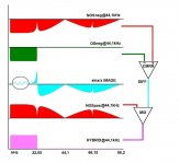
The idea is very simple. I made a sketch to demonstrate it. Suppose these are frequency response graphs. The first from top is a NOS DAC (red) and the next is an OS (green). The sketch is rough omitting details for convenience. Both need to be in phase and then are fed to a differential amp. At the output we should get the blue graph which is a copy of the ultrasonic images together with the difference between NOS and OS. Then this is mixed with another NOS in opposite phase from the original. The final outcome (pink) is a mix of NOS and OS. But since we already started from the green why should take all this twist? Call it diy fever. Certainly subjective affair... NOS has something that is pointless to determine yet ruined by the SinX/X function. Whether this method works is another story. If it is, the hybrid output should be filtered, equalized and reconstructed while retaining the properties of NOS. Is that the impulse response or anything else?
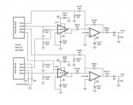
Anyway, to make it work it requires a DAC that gives NOS and OS outputs time aligned and a differential amp with sufficient CMRR at high frequencies. I built something based on DDDAC for the NOS part and another DAC with PCM1794 working in OS mode. Some very simplistic measurements suggest that the outputs are time aligned. It seems to me that the digital filter introduces a delay that it is restored by the phase registers in the DDDAC but I can't tell for sure. For the diff amp I used an INA https://www.analog.com/media/en/technical-documentation/data-sheets/AD8129_8130.pdf which by contrast with typical INAs has very good CMRR in the ultrasonic region. THD is not the best but it gets better when the signal is lower that 500mV which is the case here. I put it all together according to the schematic attached.
Seems to work for starters... It is delivering nice sound! But I guess this is not what you need to know. I tried to measure it with very limited equipment, basically a soundcard. Still far from being properly evaluated. Continued in next post.
The idea is very simple. I made a sketch to demonstrate it. Suppose these are frequency response graphs. The first from top is a NOS DAC (red) and the next is an OS (green). The sketch is rough omitting details for convenience. Both need to be in phase and then are fed to a differential amp. At the output we should get the blue graph which is a copy of the ultrasonic images together with the difference between NOS and OS. Then this is mixed with another NOS in opposite phase from the original. The final outcome (pink) is a mix of NOS and OS. But since we already started from the green why should take all this twist? Call it diy fever. Certainly subjective affair... NOS has something that is pointless to determine yet ruined by the SinX/X function. Whether this method works is another story. If it is, the hybrid output should be filtered, equalized and reconstructed while retaining the properties of NOS. Is that the impulse response or anything else?
Anyway, to make it work it requires a DAC that gives NOS and OS outputs time aligned and a differential amp with sufficient CMRR at high frequencies. I built something based on DDDAC for the NOS part and another DAC with PCM1794 working in OS mode. Some very simplistic measurements suggest that the outputs are time aligned. It seems to me that the digital filter introduces a delay that it is restored by the phase registers in the DDDAC but I can't tell for sure. For the diff amp I used an INA https://www.analog.com/media/en/technical-documentation/data-sheets/AD8129_8130.pdf which by contrast with typical INAs has very good CMRR in the ultrasonic region. THD is not the best but it gets better when the signal is lower that 500mV which is the case here. I put it all together according to the schematic attached.
Seems to work for starters... It is delivering nice sound! But I guess this is not what you need to know. I tried to measure it with very limited equipment, basically a soundcard. Still far from being properly evaluated. Continued in next post.
Attachments
Last edited:

In the left graph, HYBRID = NOSpos + DIFF = NOSpos + NOSneg - OSneg. When NOSneg = - NOSpos, HYBRID = NOSpos - NOSpos - OSneg = 0 - OSneg = -OSneg. It seems like an awfully complicated way to invert the negative output signal of the oversampling DAC. Or am I missing something, weighting factors for example?
Measurements...
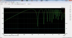
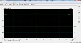
Not much to show on this... The software used needs to see a duplex soundcard. Setting for different input/output devises makes it unhappy. Especially for capturing FFT. Furthermore the soundcard adds its character. But I found stepped sine measurements to give some plausible results. First pic is NOS compared to OS. I think it is on a par with theory. Second pic is the output of the diff amp -the blue graph. I don't know how to interpret this one. It reminds me the graphs posted in DAC datasheets for the performance of the digital filter but that's all I can tell... I would appreciate if someone could enlighten me about this. The third pic is the final output. It has some minor fluctuations but it tracks well with OS signal.
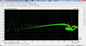
Other measurements are not so straightforward. Trying to verify time alignment, I did what I do with speakers i.e. step response. 😱 I got consistent results but maybe I'm fooled by something... Finally I tried to have a look at the aliasing images. For this I used two computers, one for the DAC working at 44,1kHz and another for the soundcard working at 192kHz. I couldn't see what I hoped. I attach the NOS and OS capture which are identical. For the hybrid output the only difference is that the ultrasonic spike is consistently lower.
All I can do is to put this to your judgement. Comments and suggestions are welcome!
Not much to show on this... The software used needs to see a duplex soundcard. Setting for different input/output devises makes it unhappy. Especially for capturing FFT. Furthermore the soundcard adds its character. But I found stepped sine measurements to give some plausible results. First pic is NOS compared to OS. I think it is on a par with theory. Second pic is the output of the diff amp -the blue graph. I don't know how to interpret this one. It reminds me the graphs posted in DAC datasheets for the performance of the digital filter but that's all I can tell... I would appreciate if someone could enlighten me about this. The third pic is the final output. It has some minor fluctuations but it tracks well with OS signal.
Other measurements are not so straightforward. Trying to verify time alignment, I did what I do with speakers i.e. step response. 😱 I got consistent results but maybe I'm fooled by something... Finally I tried to have a look at the aliasing images. For this I used two computers, one for the DAC working at 44,1kHz and another for the soundcard working at 192kHz. I couldn't see what I hoped. I attach the NOS and OS capture which are identical. For the hybrid output the only difference is that the ultrasonic spike is consistently lower.
All I can do is to put this to your judgement. Comments and suggestions are welcome!
Attachments

Last edited:
In the left graph, HYBRID = NOSpos + DIFF = NOSpos + NOSneg - OSneg. When NOSneg = - NOSpos, HYBRID = NOSpos - NOSpos - OSneg = 0 - OSneg = -OSneg. It seems like an awfully complicated way to invert the negative output signal of the oversampling DAC. Or am I missing something, weighting factors for example?
This would be the case if all signals were applied to the mixer inputs. But this is a two stage procedure hopefully preventing NOSpos/neg cancellation leaving OS untouched. Maybe I'm missing something though...
I've used AD8129 as a DAC post-amplifier and yeah it does sound good. AD8130 as shown in your schematic is going to be a bit noisy I reckon, I suggest replacing it with AD8129 with a gain of 10.
Am I right in figuring the PCM1794 has +/-4mA output so with 22R for I/V will give +/-88mV? 62mVRMS needs 62nVRMS noise for 120dB SNR. The voltage noise of AD8130 works out at 1.8uV, AD8129 gets this down to 640nV which I reckon corresponds t0 ~100dB in your implementation. You might consider increasing the 22ohm I/V resistors to improve on this.
Am I right in figuring the PCM1794 has +/-4mA output so with 22R for I/V will give +/-88mV? 62mVRMS needs 62nVRMS noise for 120dB SNR. The voltage noise of AD8130 works out at 1.8uV, AD8129 gets this down to 640nV which I reckon corresponds t0 ~100dB in your implementation. You might consider increasing the 22ohm I/V resistors to improve on this.
PCM1794 both in NOS and OS mode is working at DDDAC operating points i.e. Vcc=8V and Iref=400μA (pin 20 R=6k). This is some 10mA output current IIRC. With 22 ohm I/V I get line level ~230mV which is my target.
It's not clear to me if you built what shown in my schematic or used the AD8129 at the output of an ordinary design. You are right about noise but AD8129 cannot work in unity gain and I was not sure if I could adjust signal levels adequately. I mean I managed to control it fine with the I/V resistors.
It's not clear to me if you built what shown in my schematic or used the AD8129 at the output of an ordinary design. You are right about noise but AD8129 cannot work in unity gain and I was not sure if I could adjust signal levels adequately. I mean I managed to control it fine with the I/V resistors.
My design was much simpler than yours - just a stack of TDA1387s, half of which were fed true data and the other half, inverted data. Yes AD8129 is only good for gains of 10 or above.
Thanks! Have you posted this somewhere? I've been following your thread but got lost at some point.
No, I never wrote it up anywhere, it was rather a long time ago now. I think I was using a Muse 4*TDA1543 DAC as a basis and fitted TDA1387s on slender wires as their footprint is almost the same. I did also use AD8130 (or more likely it was AD830, the older brother to these two) at one point.
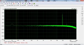
I tried to have a look at the ultrasonic range of this DAC with what I have at home... Not at all easy and I apologize for the quality of the attached graph but I think it's good for what I was looking for. A white noise file produced with audacity and played with foobar>DAC at 44.1kHz then captured by the soundcard at 192kHz using the same PC. The orange line is the NOS and clearly shows that this section works as intended. The green line is the OS, a brick wall at Fs/2. The hybrid output is identical to OS. Together with the frequency response measurements, I feel the DAC works according to the multicolor sketch of post #1. The question is what's the meaning of all this...
Think how this DAC works at 192kHz. Then the NOS and the OS signals are pretty much the same, so there won't be a blue graph. The output signal is NOS > Ri/v > opamp. For lower sampling rates this path doesn't change, only a small portion of OS is added. The final signal is not NOS and not OS either. But how much of each one is present? I'm reading about impulse response test. It is said that it's not a real life situation and it is unlikely humans to hear anything related to this. But people can tell NOS from OS solely looking at it. Unfortunately, I don't have the equipment for a high definition impulse response test.
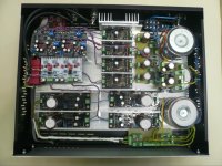
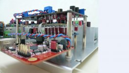
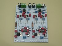
Some photos of the implementation are attached.
Think how this DAC works at 192kHz. Then the NOS and the OS signals are pretty much the same, so there won't be a blue graph. The output signal is NOS > Ri/v > opamp. For lower sampling rates this path doesn't change, only a small portion of OS is added. The final signal is not NOS and not OS either. But how much of each one is present? I'm reading about impulse response test. It is said that it's not a real life situation and it is unlikely humans to hear anything related to this. But people can tell NOS from OS solely looking at it. Unfortunately, I don't have the equipment for a high definition impulse response test.
Some photos of the implementation are attached.
Attachments
How does it sound?
Also, just noticed one little opportunity for improvement in some of the wiring. Experimentally, I found that running separate ground wires from each power supply and tying the grounds together only at the PCB end sounded better than running a shared ground wire from +- rail power supplies. The only load in my test case consisted of two I/V opamps. Both shared ground and dedicated-per-power-supply grounds were compared. Now I twist only the output and the ground wires from a single supply together, and run the twisted pairs independently of each other. What appeared to be happening was that +- rails were drawing current at different times, and current from one rail was modulating the ground voltage for the other rail. Sounded like the change reduced audible distortion a bit, but it may have actually been noise, or maybe some combination of the two. Didn't spend time trying to measure it, had bigger fish to fry.
Also, just noticed one little opportunity for improvement in some of the wiring. Experimentally, I found that running separate ground wires from each power supply and tying the grounds together only at the PCB end sounded better than running a shared ground wire from +- rail power supplies. The only load in my test case consisted of two I/V opamps. Both shared ground and dedicated-per-power-supply grounds were compared. Now I twist only the output and the ground wires from a single supply together, and run the twisted pairs independently of each other. What appeared to be happening was that +- rails were drawing current at different times, and current from one rail was modulating the ground voltage for the other rail. Sounded like the change reduced audible distortion a bit, but it may have actually been noise, or maybe some combination of the two. Didn't spend time trying to measure it, had bigger fish to fry.
Last edited:
It can be verified easily enough by disconnecting and grounding both inputs from the NOS DAC.This would be the case if all signals were applied to the mixer inputs. But this is a two stage procedure hopefully preventing NOSpos/neg cancellation leaving OS untouched. Maybe I'm missing something though...
How does it sound?
Also, just noticed one little opportunity for improvement in some of the wiring. Experimentally, I found that running separate ground wires from each power supply and tying the grounds together only at the PCB end sounded better than running a shared ground wire from +- rail power supplies. The only load in my test case consisted of two I/V opamps. Both shared ground and dedicated-per-power-supply grounds were compared. Now I twist only the output and the ground wires from a single supply together, and run the twisted pairs independently of each other. What appeared to be happening was that +- rails were drawing current at different times, and current from one rail was modulating the ground voltage for the other rail. Sounded like the change reduced audible distortion a bit, but it may have actually been noise, or maybe some combination of the two. Didn't spend time trying to measure it, had bigger fish to fry.
It sounds very nice! The striking difference is the absence of the high frequency roll off typical for NOS. In that aspect is closer to OS. But I get the feeling that it is very detailed especially for the low level recording ambience sounds, yet nothing artificial. Maybe it's my enthusiasm... I have only listened to it with headphones and this is not my best. I hope to have it hooked up to my main system for a serious evaluation in the weekend.
As for noise, please disregard the graphs I posted. It's the measuring set up that makes all this mess. The DAC is absolutely silent. Easy to change wiring for a test though. For your information, all psu digital and analog are dual mono with separate grounds per channel. Of course, grounds are met at the I2S source.
It can be verified easily enough by disconnecting and grounding both inputs from the NOS DAC.
If I understand correctly, what you mean is to leave only OS passing through the INA and then from the opamp. But then indeed the output will be the original OS.
...all psu digital and analog are dual mono with separate grounds per channel. Of course, grounds are met at the I2S source.
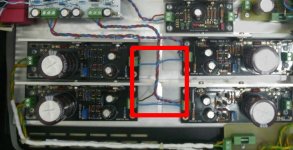
I was thinking of the stuff in the red box in the pic attached below. I found that running separate grounds for each of the + and - rails is better than a shared ground at the supplies. If you don't hear it, no problem.
Attachments
Last edited:
Verify means check that your output really as you said and not just an inverted neg from the OS DAC.
Your schema really makes very little sense.... It seems like an awfully complicated way to invert the negative output signal of the oversampling DAC...
@Markw4, yes I understand. Easy to test your suggestion. The reason I did it this way is because I think I read somewhere Salas recommending it for his regs.
Verify means check that your output really as you said and not just an inverted neg from the OS DAC.
Your schema really makes very little sense.
I think the bumping graph in post #3 verifies that.
- Home
- Source & Line
- Digital Line Level
- NOS, Oversampling... and now Hybrid(?)