Yes Mark, you are right.
That said, the 'proof by example' was refering to that phrase of mine:
That said, the 'proof by example' was refering to that phrase of mine:
GeorgeBut the electronic gear downstream the DAC may find it difficult to process the audio signal without intermodulation or even show signs of instability.
Last edited:


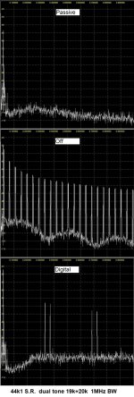
Intermodulation
Intermodulation products in general show up close to the overload/1dB compression limits. However, if the strong
signal is on the roll off of the filter, they appear well before this limit.
Aliasing
Aliasing always occurs if an insufficiently band limited signal is sampled, i.e. if the signal to be sampled contains frequencies above half the sampling frequency. Thus, aliasing is an effect showing up in many SDRs, not only in these dongles. In both types of dongles there is not much space for brick wall filters.
Image Rejection
Because the E4000 is a Direct Conversion Receiver, it has an Image Rejection problem. By switching on Correct IQ in SDR# a more or less acceptable 50dBs are reached. For the same reason, a "hump" shows in the center of the spectrum display. By using a well filtered external power supply (not from the USB connector) the hump might be reduced.
https://www.rtl-sdr.com/tag/aliasing/
https://sandsoftwaresound.net/rtl-sdr-blog-v3-hf-reception/
Just saying, one has to be careful with SDR devices. Need to make sure the problem is really in the DUT and not the test instrument.
Last edited:
True and thanks for the links.Just saying, one has to be careful with SDR devices. Need to make sure the problem is really in the DUT and not the test instrument.
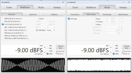
The DUT of this thread has no active circuit past DAC IC's current output up to it's line out (where the SDR was connected to).
Therefore, when intermodulation products were seen with the one type of filter from the three available but not with another, this could only mean that the instrument acting as the load to the DAC analog output was the one producing the products of intermodulation.
That was clear from the beginning. I was only surprised and cought off guard because the DAC output signal seemed to be well below the overload limit of the SDR. But still...
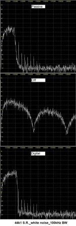
The thing here is to test the filters effectiveness to reduce the out of band noise.
And it is clear that there is a lot of out of band noise.
George
Another thing to do might be put a bandpass filter before the SDR. Then if you see signal, you know there really is something in that band.
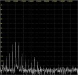
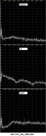
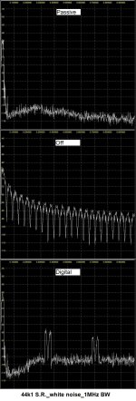
These look better although noisefloor with digital filter still has strange rise between 100kHz - 300kHz. Also the artefacts at about 350kHz & 700kHz seen with digital filter are probably due to SDR (or measurement setup).44k1 S.R._1MHz BW
Thank you bohrok2610 for your comments.
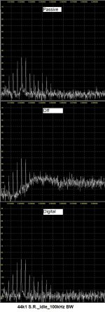
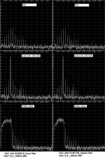
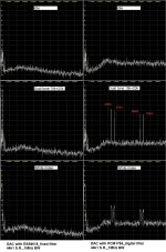
I've tried increasing the attenuation btn the DAC out and SDR input. Also I've tried reducing the test siglal level feeding the DAC. Same picture with the digital filter.
I also did the same tests with another DAC based on ESS9018.
It seems that what you've noted are not SDR or setup issues, rather are related to the digital filter of Kosta's PCM1794.
I don't know what else can I do to look further into that. I think I' leave it here.
George
Attachments

Regarding my listening impression with Kosta’s DAC, here are a few words.
Very solid sounding, good ‘body’, detailed. Dead silent too.
My preference about the filters is 1_Passive. 2_Off. 3_Digital
Off (NOS) sounds very organic with acoustic instruments, natural sound decay but on complex music loses some discrimination btn instruments.
Digital is of tight control. The desirable setting with rock and electrical instruments music. With classic, is a bit of ‘dry’.
The Passive has a right mix of NOS palpableness and Digital’s precision.
Overall, a unique three filter experience (with the rest of construction as common, so a true feasible comparison btn filters), combined with an A+ audio performance (haven’t found a weak spot there), an equally good construction (a lot of “iron” and full of shunt voltage regulators), feel and looks.
I would only like it to have a higher analog out signal level ( 0.658Vrms @0dBFS digital input). But I think this lowish output was Kosta's decision based on his system's gain structure.
My compliments Kostas. I wish you take as much pleasure listening through it, as much you experienced designing and building it.

George
Very solid sounding, good ‘body’, detailed. Dead silent too.
My preference about the filters is 1_Passive. 2_Off. 3_Digital
Off (NOS) sounds very organic with acoustic instruments, natural sound decay but on complex music loses some discrimination btn instruments.
Digital is of tight control. The desirable setting with rock and electrical instruments music. With classic, is a bit of ‘dry’.
The Passive has a right mix of NOS palpableness and Digital’s precision.
Overall, a unique three filter experience (with the rest of construction as common, so a true feasible comparison btn filters), combined with an A+ audio performance (haven’t found a weak spot there), an equally good construction (a lot of “iron” and full of shunt voltage regulators), feel and looks.
I would only like it to have a higher analog out signal level ( 0.658Vrms @0dBFS digital input). But I think this lowish output was Kosta's decision based on his system's gain structure.
My compliments Kostas. I wish you take as much pleasure listening through it, as much you experienced designing and building it.
George
Last edited:

- Home
- Source & Line
- Digital Line Level
- NOS, Oversampling... and now Hybrid(?)