hi all,
hi all,
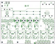
this is the new power supply jmep image of the PCB.
improve stefanobilliani advise,
the ground loop was improve more, relayout all the ground area in the [power supply area. I use 96db speaker full range & 94 db ( TAD speaker) & test low noise. The original also no problem in normal speaker. Only high efficiency will little noise.
1. New layout of the power supply.
2. increase the capacitance of the caps before the diode from 3300uf >>>>4300uf+0.1ufMKP ( 3300+1000+0.1MKP). or if diyers still like to increase more. (3300+2200+0.1ufMKP)
I was so sorry that if I use too large capacitors te sound will little lower. or I will advise paralell two 470uf on the 3300uf & 1000uf caps. ( use BC philips & test good)
I use ,my friend with 2X15inch woofer & horn(2'throats to test)& alnico tweeter for more dynamic sound & noise, over 97db.
If the capacitor was too large, the sound will little slow. So if U heard classis & more dynamic music will not so good.
3. All the isolated power transformers was mould into the pcb. approx no cable seen into the dac.
New power supply test in high efficiency speaker with quite quiet.
will supply to market on 2006-09-20.
thx
thomas
hi all,
this is the new power supply jmep image of the PCB.
improve stefanobilliani advise,
the ground loop was improve more, relayout all the ground area in the [power supply area. I use 96db speaker full range & 94 db ( TAD speaker) & test low noise. The original also no problem in normal speaker. Only high efficiency will little noise.
1. New layout of the power supply.
2. increase the capacitance of the caps before the diode from 3300uf >>>>4300uf+0.1ufMKP ( 3300+1000+0.1MKP). or if diyers still like to increase more. (3300+2200+0.1ufMKP)
I was so sorry that if I use too large capacitors te sound will little lower. or I will advise paralell two 470uf on the 3300uf & 1000uf caps. ( use BC philips & test good)
I use ,my friend with 2X15inch woofer & horn(2'throats to test)& alnico tweeter for more dynamic sound & noise, over 97db.
If the capacitor was too large, the sound will little slow. So if U heard classis & more dynamic music will not so good.
3. All the isolated power transformers was mould into the pcb. approx no cable seen into the dac.
New power supply test in high efficiency speaker with quite quiet.
will supply to market on 2006-09-20.
thx
thomas
Attachments
Hi stefanbollini,
I have tried your suggestions to get rid of the noise in the dac, but there does not appear to be a difference in the noise I can hear. I'm testing this with my headphones on, to be a bit more accurate. Anyway, if I understand you correctly, there are three grounds that needs to be disconnected. On the main board it is at J80, J24 and J75, correct? I have simply bent the long pins a bit so that they do not plug back when the board is re-inserted. Has anybody else tried some other methods? I have tried asking Thomas for the schematics, but he does not appear to want to give it to us, so I'm flying kinda blind here...
Any help would be appreciated.
Thanks
Gert
Hi Thomas,
That is just the area around the TDA1541. I need the schematics for the entire board as you supplied it to us. Please be so kind as to indicate to me where you posted the schematics a previous time and I will refer to that.
Thanks
Gert
That is just the area around the TDA1541. I need the schematics for the entire board as you supplied it to us. Please be so kind as to indicate to me where you posted the schematics a previous time and I will refer to that.
Thanks
Gert
Sorry Thomas,
I was a bit quick to reply. I did not know you sent the diagrams in many parts.
Thanks, I think that is everything...
Gert
I was a bit quick to reply. I did not know you sent the diagrams in many parts.
Thanks, I think that is everything...
Gert
Thomas,
I think this GB is finished? If so, can I go on the lsit for the next one?
Cheers,
Paul
I think this GB is finished? If so, can I go on the lsit for the next one?
Cheers,
Paul
hi wineds,
this will had another ultimate version coming ca choose single chips or parallel chips. I was considerate that produce full balance versions or parallel versions.
BTW, this several days I try the full balance in several audio setup all were over 96DB to test the dynamic & noise, this is dead silent, * use headphone to test too.
thx
thomas
hi,
AD1865 full balance DAC will arrive tomorrow. I will test the sound quality & mainly use headphone to test the noise.
thx
thomas
AD1865 full balance DAC will arrive tomorrow. I will test the sound quality & mainly use headphone to test the noise.
thx
thomas
Hello Thomas,
I've recieved the cd-controler, thank you very much !
My brother is interested in this controler as well, do you still have them in stock ?
Thanks,
Nico
I've recieved the cd-controler, thank you very much !
My brother is interested in this controler as well, do you still have them in stock ?
Thanks,
Nico
hi Tubelover
i've contacted you on ebay also. i would like to buy 1/2 depending on price of the tda1541a/S2's. do you have any left? if not are you going to buy any more , i'd be happy to do a GB.
thanks
matt
i've contacted you on ebay also. i would like to buy 1/2 depending on price of the tda1541a/S2's. do you have any left? if not are you going to buy any more , i'd be happy to do a GB.
thanks
matt
hi wandermatt,
I will confirm your order if next stock of 1541aS2 arrived.
this is the last 10 pcs. not more.
wait a moment pls.
thx
thomas
I will confirm your order if next stock of 1541aS2 arrived.
this is the last 10 pcs. not more.
wait a moment pls.
thx
thomas
- Status
- Not open for further replies.
- Home
- Group Buys
- non-profit ver.3 TDA1541a DAC for limited budget diyers