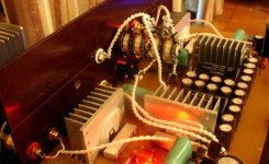
This is my "testing rig", it serves only for sound evaluation.
There were some changes in the schematics, R4=7k5, R3=340R, voltage amplification nearly 22dB.
There were some changes in the schematics, R4=7k5, R3=340R, voltage amplification nearly 22dB.
Attachments
Last edited:
We have carried out listening tests of this prototype amp, me and five other persons, by using it
1) as a headphone amp, and
2) as a preamp to the Modified Follower with HF transistors.
We compared to Perreaux Silhouette SXH2 headphone amp (with Audio Technika ATH-AD2000 headphones). The prototype easily wins (including opinion of Perreaux Silhouette’s owner).
The prototype + Modified Follower with HF transistors wins also against SE 300B tube amp (votes 6 vs 0), against push-pull tube amp (votes 5 vs 1), against Yamaha B-2x top-level vintage amp. The SE 300B amp is internationally recognized one, from ERAUDIO.
The rest of the system’s components are: PMC EB1i, Shanling CD-T1500, Stereovox 600 speaker cable, Analysis Plus Silver Oval In interconnect.
Hi Vladimir,
Can You please describe in few words the sound of your NFB preamplifier.
Thanks
Key words for sound impressions - extreme transparency and microdetails (brass sound like from very very good tube amps) , pleasant sound in all frequency ranges (not surprisingly it wins in bass region, but also mids are more consistent than from tube amps).
Thank you very much, I was waiting for you to be sure in your design that it sound good. Now i can start to build the NFB preamplifier for my power follower 99 (not modified). In this moment im using NFB tube preamp, first stage-gain and the second one is catode follower. Im really interested if your NFB preamp will sound better.
Do you have any intention to make some mods on your preamp? If yes, i should wait longer.
Best regards
Goran
Do you have any intention to make some mods on your preamp? If yes, i should wait longer.
Best regards
Goran
Thank you very much, I was waiting for you to be sure in your design that it sound good. Now i can start to build the NFB preamplifier for my power follower 99 (not modified). In this moment im using NFB tube preamp, first stage-gain and the second one is catode follower. Im really interested if your NFB preamp will sound better.
Do you have any intention to make some mods on your preamp? If yes, i should wait longer.
Best regards
Goran
The design is very simple and stable, sounds excellently. The only thing - one needs at least 10 pcs of input J103BL for decent pair selection.
One more possible improvements - make an integrated amp from the No NFB preamp and your follower-99, in this case you connect galvanically pre out and amp in, two more pluses for sound. Also make a cluster-like output cap for the follower.
Thanks for your suggestions Vladimir. I agree with idea- about integrated amplifier. One capacitor less. About cap-clusters i would like to ask you, what value of single cap would be the best? I remember (if im not wrong) in your modified follower you have 680uF per cap.
Thanks for your suggestions Vladimir. I agree with idea- about integrated amplifier. One capacitor less. About cap-clusters i would like to ask you, what value of single cap would be the best? I remember (if im not wrong) in your modified follower you have 680uF per cap.
I believe one will not make a mistake by using 16...20 pcs of Elna Silmic 1000uF x 63V, plus 68uFx400V Mundorff polyprop shunt.
Thanks Vladimir
I hope it wont be a problem to ask you for advices durring building process.
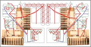
I do not use PCB, as already mentioned, but before drilling and soldering I try to create a picture of connections and parts locations, something similar to PCB drawing. Sometimes it is undestandable to me only, but I promise to post this drawing, maybe it could be of some use for others.
For this project i will use PCB. I will need some time to design it. Avoiding output capacitors will provide smaller PCB.
Hi Vladimir!
Could you advice equivalents for 2sk2199?
Decent substitute for k2199 (Ciss=80pF) could be simply IRF610 (Ciss=135pF), with some minor loss in performance.
Other more exotic and more expensive variants exist, but for different wattages and voltages.
Here I eclose the picture of parts locations and connections. It is not very dense packed, because of the heatsinks, but No NFB assist to avoid any parasitic oscillations. Most of parts are soldered pin-to-pin, other connections are made by twisted 0,6mm copper wire in teflon.
Attachments
Vladimir, you are avoiding PCB, from what reason? Do you think sound is better with point to point wirring aproach? I dont think there will be difference.
Vladimir, you are avoiding PCB, from what reason? Do you think sound is better with point to point wirring aproach? I dont think there will be difference.
Without PCB, number of solder joints is almost half of that with PCB. Each solder joint contributes to that "effective total signal path" becomes a bit longer. This effect definitely is not measurable, but quite listenable, within ultimate sound quality domain.
The picture No.1 on your first post.. do you have a photo from the bottom side of PCB? Its not my intention to copy it, but im interested how you connect the parts.
The picture No.1 on your first post.. do you have a photo from the bottom side of PCB? Its not my intention to copy it, but im interested how you connect the parts.
I'll try to post, but its nothing noticable, just bend pins to each other, then decide how to locate and to bend the pins ends, then fix them and solder. Not too much aestetics, but quite an effective way.
- Status
- Not open for further replies.
- Home
- Amplifiers
- Solid State
- No NFB Headphone/Pre Amp