I've been simming Nelson's Zen V3 voltage regulator. Simple, brilliant.
0.32 ohm load
21 amp/6.7 volt output (my differential follower amp doesn't use much voltage)
0.2 mV ripple (using 6800uF cap in mosfet gate R/C network)
0.6 mA ripple (I hope the sim is correct, wow)
It doesn't take a genius to guess what I'm going to do...
0.32 ohm load
21 amp/6.7 volt output (my differential follower amp doesn't use much voltage)
0.2 mV ripple (using 6800uF cap in mosfet gate R/C network)
0.6 mA ripple (I hope the sim is correct, wow)
It doesn't take a genius to guess what I'm going to do...
I see that the regulated voltage can be modulated. This way the amp's output can climb above the regulated voltage. Beautiful!
Nelson Pass said:
If you want a power gyrator, you can consider using a single-ended
power Mosfet or complementary push-pull power Mosfets as followers, with the Gate(s) being the + terminal corresponding to the op amp.
😎
I'm wrapping my mind around this concept over a cup of coffee... it's very cool. So, I'm thinking:
With a power differential follower, such as my amp, the output ripple is so low my meter can't read the fluctuations. I can read the 30mV ripple in the power supply feeding it. Now, this power amp could energize another differential power amp. Am I on to something? The end result might be almost no ripple at all. The gates of the first follower are controlled by a hiqh quality regulator, op amp, or zener diode. All in all, my initial impression is that it's another way of looking at what was done in ZV3. What do you guys think?
I think (... and it still hurts!) that you're getting toooooo complicated. The gyrator suggestion was intended as an "artificial inductor", not a migrane!
As a substitute that can be organised into a low(er) loss, more linear behaviour than a large high Q choke to save you bending the copper into little circles! (Save that for your Xover units, that's bad enough!)
It'll still use up a lot of power in high current use (still stuck wit' the lunch bill!) and keeps that ol' meter ticking over!
' the best ...
This is the differential noise going to your speakers with no input?
Whole lot of nothin' much at about 100nV!!
Seems to accur at 0.1sec - looks a bit like diode rectifier bleed noise (Shottky?) - maybe can dump this too with diode snubberS? The sims are marvellous tools to play with!
Whole lot of nothin' much at about 100nV!!
Seems to accur at 0.1sec - looks a bit like diode rectifier bleed noise (Shottky?) - maybe can dump this too with diode snubberS? The sims are marvellous tools to play with!
jameshillj said:This is the differential noise going to your speakers with no input?
Whole lot of nothin' much at about 100nV!!
Seems to accur at 0.1sec - looks a bit like diode rectifier bleed noise (Shottky?) - maybe can dump this too with diode snubberS? The sims are marvellous tools to play with!
You're so smart 😀
I'm simming with MUR810 diodes, and have the amp's input signal turned off. With the output noise being this low, I'm not to concerned about snubbers other than an exercise in absolute perfection.
Perhaps I'll take you up on your suggestion.... just for kicks.
Aren't simulators a blast?! Best learning tool I've ever used.
Just out of curiosity, would you have the SIM cct for the Cree diodes - I tried them in the F3 instead of either the MURs,r the BYW29 or the 08ETH06s and found they produced a rather "choked off" dull sort of sound, with/without snubbers and with a number of different smoothing caps - never did get to the bottom of it!
With noise as low as this, who cares where it comes from!
Dunno if the program can seperate the supply sim when running the amp at capacity, say a 10kHz square inout signal - might show a different story, but be quite interesting if you can do it.
I once had a look at the supply rail running a class A amp about 70%max - very dissapointed - current spikes and hi freq noise all over the place - it's quite a surprise how well the simple Cmultiplier worksd on the rails - got me thinking about a full house shunt reg! (for the F3!)
What's another couple of hundred watts, or so, to keep me warm!
jameshillj said:
What's another couple of hundred watts, or so, to keep me warm!
That's why we call it art...

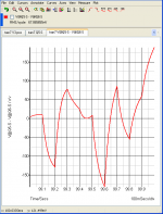
In my sim I use a transformer and bridge to energize the amp I'm designing. The sim does a good job of displaying the various ripple and noise distortions.
No big deal, yes, but I discovered that I can get an even cleaner output (than the pic posted in my earlier post) if I use the sim's perfect voltage source for bias voltage.
The idea being that perhaps bias voltage should be highly regulated vs. using raw voltage from the amp's PS.
I've posted a pic of the differential voltage output (zero volts at input) using this concept. It's ridiculously low in noise, no real world supply would be this perfect, but it demonstrates that the output can be even cleaner than the last pic I posted in post 166...
femto: le -15 or: 0.0000000000000175 VRMS
Attachments
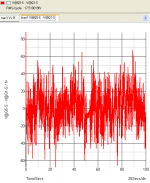
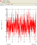
I just discovered that the new sim I sat up for the previous post didn't have the "real time noise" button box checked. This meant I was comparing apples to oranges. The results were misleading--sorry!
With the "real time noise" enabled, I have more accurate information. There is still a definite improvement in noise reduction with a cleaner (highly regulated) bias voltage source:
With the "real time noise" enabled, I have more accurate information. There is still a definite improvement in noise reduction with a cleaner (highly regulated) bias voltage source:
Attachments
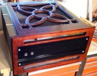
If that beautiful boat anchor weighs anywhere near what I suspect it does, you're going to need some serious handles. Something like Papa uses on his amps.
I have a thought about your inductors, why not put them in an oil bath? This is what the power companies do with many of their transformers and phase correction chokes. Unless the oil is contaminated, it's not electrically conductive, and it does help dissipate heat. Use an enclosure for the transformer/oil well that is made from aluminum, with some heatsink material attached to the outside. You might be able to get away with using a smaller gauge wire, thus lowering the mass. Just a thought.
Peace,
Dave
P.S. Or you could use the same size coil in oil, and then you can run more current through it! 😀
dave_gerecke said:... why not put them in an oil bath?...
What a cool idea! (no pun intended) It can't be that tough to make a box out of heat sinks, then add a top and bottom cover. This amp is supposed to be unique. With regards to homebrew DIY, that sounds like a one-of-a-kind concept. 😀
Call your local electrical supply house that electricians use and they can probably even supply you with real transformer oil.😎
If you really want to get crazy you could put the main transformer(s) in an oil bath also!
MUST HAVE MORE POWER!!!
Oops, sorry, got a little carried away there. And now back to our regularly scheduled insanity.
Peace,
Dave
If you really want to get crazy you could put the main transformer(s) in an oil bath also!
MUST HAVE MORE POWER!!!
Oops, sorry, got a little carried away there. And now back to our regularly scheduled insanity.
Peace,
Dave
incredible work on the case. If you are going to go ahead with the oil bath idea. Make sure the oil you use is suitable. I'm not sure regular 10W30 is good enough. The temp range is the issue. I would just hate to see the oil ignite and take the amp and the house it is in with it.
DaveM makes a good point here. I did a brief search on the 'net for the flashpoint of 10w30 oil and the lowest I found is 200F, or around 93C. But the other thing that will come into play here is the vapor pressure if you put the transformer in an oil bath and enclose it. If you don't put in a vent to allow for pressure relief, then eventually you will burst the seal. When this happens it's possible that the oil is at a temp that it will auto ignite. Perhaps it would be best to use actual transformer oil, and make sure that there is expansion space in the oil bath container, and a proper pressure vent.
Peace,
Dave G
Peace,
Dave G
Thanks for the tips, Dave and Dave.
I wouldn't consider using anything less than an approved product. BTW, the chokes don't get over 90C.
I appreciate the wonderful comments. 🙂
I wouldn't consider using anything less than an approved product. BTW, the chokes don't get over 90C.
I appreciate the wonderful comments. 🙂
carpenter said:Thanks for the tips, Dave and Dave.
I wouldn't consider using anything less than an approved product. BTW, the chokes don't get over 90C.
I appreciate the wonderful comments. 🙂
I would, but when I get around to actually doing something, I'm a bit of an experimenter.😉
I a bit embarrassed that I didn't think about the possibility of combustion/explosion. I was trained as a HAZMAT tech by my employer years ago, so I should have been thinking of the safety side of things, but I was only thinking of the electrical side of it. Of course, keeping the chokes in an oil bath will lower the temp, so this modulates the issue some.
Peace,
Dave
- Status
- Not open for further replies.
- Home
- Amplifiers
- Pass Labs
- No more aching back