Re: Re: Conundrums and Escher Schematics
Absolutely. Anybody interested in Gibson also has to read
the rest of that trilogy, "Count Zero" and "Mona Lisa Overdrive".
Gibson constructs some of the most beautifully crafted sentences
to be found in the English language.
As another side note, some of Goldfrapp is musically
pointing in the same direction. 😎
Cradle22 said:"Wintermute" is the AI in William Gibsons excellent 1984 "Neuromancer", which defied all boundaries of classical SF, and is one of the few SF books actually recognized as true literature by the critics...
Absolutely. Anybody interested in Gibson also has to read
the rest of that trilogy, "Count Zero" and "Mona Lisa Overdrive".
Gibson constructs some of the most beautifully crafted sentences
to be found in the English language.
As another side note, some of Goldfrapp is musically
pointing in the same direction. 😎
To me this circuit seems very simple...
...so how about double crossed feed forward
Some might call it X feed forward
More confusion soon 😉
...so how about double crossed feed forward
Some might call it X feed forward
More confusion soon 😉
???
double crossed gives only -132dB across load and left/right outputs -64dB each.
I removed the double cross on the double cross schematic and get -123dB across load and left/right outputs -120dB each.
After remove it looks like X-amp SE ClassA but no Rmagic and no feedback to other side.
I still do not trust absolut values but it shows what happens.
johnferrier said:Success?
JF
With what ?
The sim works now.
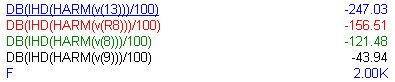
According to sim, left amp -121dB (own distortion) and right amp -44dB (own distortion + error signal) sould add to -156dB distortion across the load.
If this is so in the real world I non't know yet, but I plan to build and test it soon.
Bernhard
Bernhard said:If this is so in the real world I non't know yet, but I plan to build and test it soon.
Bernhard
please keep us posted.
I own experience with my modification on jlh1969 is that people tend to tell you "no" even if they cannot articulate why. if it works in simulations, you have a shot at getting it to work in real life.
I would say build it and you may have yourself positively surprised.
another 12dB
Had an idea today for a new complicatification of my circuit
It concerns both sides.
Did it to one side and we're talking about
-168.24dB
Had an idea today for a new complicatification of my circuit
It concerns both sides.
Did it to one side and we're talking about
-168.24dB
Applied modification to other side too, and...
-183,30dB
I promise to stop @ 200 😛
Total op amp count: 7
-183,30dB
I promise to stop @ 200 😛
Total op amp count: 7
Set voltage gain of standard distortion killer circuit from originally 1 to about 4.
After fiddling resistor values:
K2 = -230 dB ( before was -156 dB )
K3 = -156 dB ( before was -156 dB )
After fiddling resistor values:
K2 = -230 dB ( before was -156 dB )
K3 = -156 dB ( before was -156 dB )
Bernhard,
I've just read this post for the first time. I think your idea is really interesting and thought provoking and your focus on the numbers is great.
When I look at this circuit I see it as a standard feedback amp except that the feedback signal takes a separate path to the main amp. This is interesting in itself. The question is, why should it be better to feed the correction signal through a separate amp?
Well, one reason would be if the feedback amp is more linear than the main amp for most error signals. As you've pointed out, the better the main amp the smaller the error signal, or in other words, the less power in the error signal and so you should be able to make the correction amp of much lower power handling than the main amp. If the latter results in a significantly more linear amp then you've really got something!
As has been pointed out the correction amp needs to have the same current capability as the main amp. Generally it is the current capability that encourages distortion so you'll have to think hard about this. You'll find a way!
traderbam said:
When I look at this circuit I see it as a standard feedback amp except that the feedback signal takes a separate path to the main amp. This is interesting in itself. The question is, why should it be better to feed the correction signal through a separate amp?
Where do you see a separate feedback path ?
Both amps got their own feedback.
The left amp works just as normal amp, there is nothing special.
Just the right one on its inputs subtracts the left input signal from the left output signal, so if there is something on the left side that should not be there, it will appear on the right side also and cancel.
This is not feedback, it is subtraction.
To my understanding with feedback there is an undefined regulation process and the signal runs endless in circles, always being reamplified, creating higher order distortions everytime.
Here beside the local feedback of each amp, there is a one way path from left to right and the signal travels one time only, not in circles.
To be honest, I know 90% only what happens here and the rest...

I did a comparison of amp schematics and this is what I got:
This circuit with different values of resistors:
a, K2 = -230 dB K3 = -156 dB For sure K2 can go down to -247 dB...
b, K2 = -156 dB K3 = -156 dB
AlephX Hugo's schematic:
K2 = -163 dB K3 = -89 dB
My SE classA monolytic susy amp:
K2 = -247 dB K3 = -131 dB
Extended version of this circuit:
K2 = -175 dB K3 = -158 dB (Resistors not fiddled yet....)
All outputs across load 8Vpp 🙂
Guess it's "Feedforward"
Basically, instead of feeding just an error signal back through the - input of the amplifier (feedback), your right amplifier feeds an error "correction" signal to the - input of the load ("feedforward"). It doesn't correct for errors in the right amplifier and small time delays in the feedback path cause it to not work perfectly. Noise from two amplifiers may be higher. Also, I wonder what is happening when you feedforward a correction signal to the opposite end of a load that is also inductive (rather than pure resistive as your model). I don't know if it makes a difference.
What does "feedforward" sound like? Certainly, someone has tried this.
JF
I am not an expert on amplifier design, but i do see some potential problems with this.
I do not see any way to compensate for the time difference between the input and the output.
Say for example there is a rapid spike of "distortion" the compensation amp would output the inverse of this spike slightly after the first one occurred. which would just add more distortion.
Also the difference amplifier would be measuring the difference of the input and the output after it had been amplified. so rapidly rising music signals could be deadened because they were falsely identified as distortion.
Having the output of the main stage driving in to a varying load may cause it output characteristics to change while the difference amplifier is active, which the differnce amplifier would then detect, causing yet another change. possibly causing feedback.
now the response may be so good that all these problems happen outside the audible range, but the fact that they are going on could surely affect the sound in some way.
Nelson Pass said:I vote that we change the name of this thread to:
no mercy simulator killer circuit
😉
I would be very happy to hear constructive complaints about the circuit 🙄
____________________________________________________________
It is possible to let the right side swing signal also.
With 50% of left side amplitude I can get K2 as low as normal, but K3 and higher gets worse

Concerning delays I think the problem is not a bigger one as with normal feedback.
neutron7 said:
Say for example there is a rapid spike of "distortion" the compensation amp would output the inverse of this spike slightly after the first one occurred. which would just add more distortion.
Also the difference amplifier would be measuring the difference of the input and the output after it had been amplified. so rapidly rising music signals could be deadened because they were falsely identified as distortion.
A positive spike on the left output will cause a positive spike on the right output, not inverted.
Look at the Supersymmetry
also the output is fed back to the other side, similar problem if it is (was) one.I think a few people would be very happy to read about how this actually sounds like (instead of only spice reports).
I've started using spice (LTSpice at home and PSpice at work) and there is no way this is the same as a real circuit. It certainly is another way to study the circuit. I like that, but...
For one, I can't actually smoke something. And I know there is smoke analysis, but sometimes I want to see the resistor change value and fuse (then I know that something is happening beyond basic simulator calculations). Maybe in future spice programs.
JF
johnferrier said:I think a few people would be very happy to read about how this actually sounds like JF
Yes, I will built it and listen and measure.
This is not feedback, it is subtraction.
A candidate for DiyAudio.com quote of the week.
 🙂
🙂- Status
- Not open for further replies.
- Home
- Amplifiers
- Solid State
- no mercy distortion killer circuit