Nelson,
thanks for your comment, but I would be really happy about your opinion, wether this circuit will work good or not, and why. 🙄
By the way, I tried to X it by 47k feedback from +inputs of op amps to other sides, it slightly decreased the ability to cancel clipping.
For my new vintage spectrum analyzer the smallest detectable signal is -70dB, -75dB with background subtraction.
Is that good enough for amp testing ?
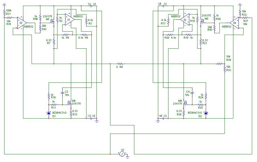
Slightly modifivated schematic:
thanks for your comment, but I would be really happy about your opinion, wether this circuit will work good or not, and why. 🙄
By the way, I tried to X it by 47k feedback from +inputs of op amps to other sides, it slightly decreased the ability to cancel clipping.
For my new vintage spectrum analyzer the smallest detectable signal is -70dB, -75dB with background subtraction.
Is that good enough for amp testing ?
Slightly modifivated schematic:
Dear Bernhard,
we have to resolve this problem.
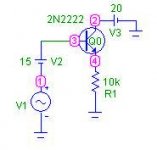
In that follows I’ll refer to the attached circuit.
I am using MC7 demo ver. 7.1.6 but it does not matter. The device (2N2222) is part
of small.lib I think. The generator is set for 1k Hz freq. and 5 Volts amplitude, internal res
set to zero. The other quantities are on the schematic.
I run transient analysis on it following the procedure given in message #52 but now I’ll start with
harm(v(1)), that is the generator, and harm (v(4)), the output.
we have to resolve this problem.
In that follows I’ll refer to the attached circuit.
I am using MC7 demo ver. 7.1.6 but it does not matter. The device (2N2222) is part
of small.lib I think. The generator is set for 1k Hz freq. and 5 Volts amplitude, internal res
set to zero. The other quantities are on the schematic.
I run transient analysis on it following the procedure given in message #52 but now I’ll start with
harm(v(1)), that is the generator, and harm (v(4)), the output.
Attachments
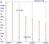
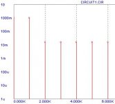
Harm () function
As you can see the distortion components of the generator (v(1)) are negligible ( amplitude <3 pV)
The plot shows a near 5Volt fundamental for v(4) ( 1k Hz component) than we have
2k Hz at 800 uV 3k Hz at near 100uV and so on. Also you can read at 0 Hz a value 14.35 that is
the bias.
So we note, for instance, a 2nd harmonic of 800u/5 *100 = 0.016 %. But the program can make these calculation for us if one use the function ihd ( not thd).
Attachments
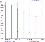
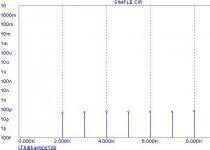
Ihd(Harm ()) function
Pay Attention: the values at freq = 0 and 1k do not matter. Some times 0 sometimes 1.
At 2k, for instance, we read 0.016 (16m) that is the percentage value of 2nd order distortion as expected. If we feel better with decibel we have to use the func. Db().
Pay Attention: the values at freq = 0 and 1k do not matter. Some times 0 sometimes 1.
At 2k, for instance, we read 0.016 (16m) that is the percentage value of 2nd order distortion as expected. If we feel better with decibel we have to use the func. Db().
Attachments
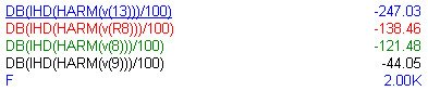
Db(Ihd(Harm ())/100 ) function
remember to divide per 100 before apply db(), that is db(*/100) since ihd() gives percentage values.
This time we have to change the limits of Y-range to 0,-260 and click on right button to unlog the graph. We finish with a top-down graph. The 2nd harmonic of the generator is at –247 db while we found 2nd harm of v(4) at –76db ( that we know is .016% ).
Now we switch from individual harmonic distortion to total harm dist. With the function THD(harm())
Attachments
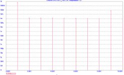
Thd(Harm ()) function
We, again, change the value of Y – range to 10, 1u and click to LOG graph.
In this case we have a series of quasi equal line owing to the small high components.
At 2k we find, as before, 0.016 at 3k 0.0161 that remain constant. This is cumulative distortion relative to the first N harmonics. For N great, in this case for instance 10 (10k) or 50 (50k) we have total harm distorsion.
I hope these help
Let me know
Federico
Attachments
Hi,
I just start reading, could you please try THD(HARM(v(V1))) ?
It gives me 60m for positive halfwave 🙁
I just start reading, could you please try THD(HARM(v(V1))) ?
It gives me 60m for positive halfwave 🙁
Hi
I do not figure out what you mean with
positive halfwave.
Those functions have to be applied at least to
a full period ( I use the interval 4m, 5m that
is the period for a 1k wave). If not they are meaningless.
In the x-axes you must use frequency not time.
Set all the values as in message #52.
bye
Federico
Something is wrong. For a naked sine source I get -71dB for 2nd harmonic 
I made a fresh circuit, only a sinesource connected to ground on one side, other side open. and I get -71dB. I click on I and with I I click on the Sine source and in the text window (F=1k A=5)
What else can I do ?
5) maximum time step = 0.001/1024 That does not work for me, I can only make 0.001
I made a fresh circuit, only a sinesource connected to ground on one side, other side open. and I get -71dB. I click on I and with I I click on the Sine source and in the text window (F=1k A=5)
What else can I do ?
5) maximum time step = 0.001/1024 That does not work for me, I can only make 0.001
Bernhard,
I'm not following what is going on, but I see a lot of weeping here.
Are you trapped? (Werden Sie eingeschlossen?)
JF
I'm not following what is going on, but I see a lot of weeping here.
Are you trapped? (Werden Sie eingeschlossen?)
JF
Conundrums and Escher Schematics
Hello Nelson,
I was not aware you are such a humorous guy😉
I had to reach for the dictionary to find the meaning of conundrums. Be aware Escher was a genius.....Will never forget the term Escher schematics. 😉
Abbreviations always pose a problem for non-native speakers. Could you enlighten me on that one, meaning AI? 😀
😀
Nelson Pass said:I have decided that Bernard is an AI, kin to Gibson's Wintermute
or Continuity. He has taken it unto himself to confuse us with
conundrums and Escher schematics.

Hello Nelson,
I was not aware you are such a humorous guy😉
I had to reach for the dictionary to find the meaning of conundrums. Be aware Escher was a genius.....Will never forget the term Escher schematics. 😉
Abbreviations always pose a problem for non-native speakers. Could you enlighten me on that one, meaning AI?
😀Bernhard,
the problem is probably in the maximum time step
it must be set in that manner. .001 is a too big value.
I do not understand why when you write .001/1024
the program doesn't work.
However if you send me (privately) your e-mail
addres I'll send you the .cir file.
the problem is probably in the maximum time step
it must be set in that manner. .001 is a too big value.
I do not understand why when you write .001/1024
the program doesn't work.
However if you send me (privately) your e-mail
addres I'll send you the .cir file.
johnferrier said:Bernhard,
I'm not following what is going on, but I see a lot of weeping here.
Are you trapped? (Werden Sie eingeschlossen?)
JF
No, I am not trapped, may be you should read the posts before posting 😉
Yes, lots of
, but that has nothing to do with my circuit...fscarpa58 said:Bernhard,
the problem is probably in the maximum time step
it must be set in that manner. .001 is a too big value.
I do not understand why when you write .001/1024
the program doesn't work.
However if you send me (privately) your e-mail
addres I'll send you the .cir file.
Very good idea, may be we should exchange .cir
Re: Conundrums and Escher Schematics
Hi!
AI = Artificial Intelligence, a thinking computer.
"Wintermute" is the AI in William Gibsons excellent 1984 "Neuromancer", which defied all boundaries of classical SF, and is one of the few SF books actually recognized as true literature by the critics...
Just some side info...
Bye,
Arndt
Hi!
Elso Kwak said:
Hello Nelson,
I was not aware you are such a humorous guy😉
I had to reach for the dictionary to find the meaning of conundrums. Be aware Escher was a genius.....Will never forget the term Escher schematics. 😉
Abbreviations always pose a problem for non-native speakers. Could you enlighten me on that one, meaning AI?
AI = Artificial Intelligence, a thinking computer.
"Wintermute" is the AI in William Gibsons excellent 1984 "Neuromancer", which defied all boundaries of classical SF, and is one of the few SF books actually recognized as true literature by the critics...
Just some side info...
Bye,
Arndt
Ok, got it, thanks Federico 🙂
Just my computer
 🤐 , takes 30s to run. Never waited so long 🙄
Still do not understand what the 0.001/1024 is good for.
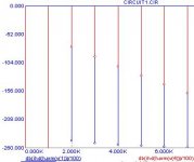
Here is the result: Distortion across load: 17dB better performance with error amp compared to left amp alone.
I also tried feedback to the other side, not so good in this particular case.
Higher bias on the right side gives better results...
Swapping NE5532 to opa627 changes nothing.
I will try to improve it further.
Bernhard
Note: Adding black to green gives red
Blue is sine source
Red is voltage across load
green is left amp output
black is right amp output
Just my computer
🤐 , takes 30s to run. Never waited so long 🙄 Still do not understand what the 0.001/1024 is good for.
Here is the result: Distortion across load: 17dB better performance with error amp compared to left amp alone.
I also tried feedback to the other side, not so good in this particular case.
Higher bias on the right side gives better results...
Swapping NE5532 to opa627 changes nothing.
I will try to improve it further.
Bernhard
Note: Adding black to green gives red
Blue is sine source
Red is voltage across load
green is left amp output
black is right amp output
Attachments
Happy for you, Bernhard
Think about this:
.001 seconds is the period of 1k sin wave. If you set maximum time step =.001 then the algorithm will use, say, a step from .001/10 up to .001/50 (variable). You see more points because the algorithm interpolates by means of some polynomials or spine curve.
But if I have toperform an FFT ( function harm()) of the signal I need 1024 ( or maybe less, eg 512 or 256, you can try) of good (calculated not interpolated) points. So by setting max time step=.001/1024 you force the algorithm to make more calculation and giving precise values to the FFT algorithm.
To speed up things you can try to put 256 in the DSP parameters form
Upper time limit= 3m and lower time limit =2m in the same form
A max time step of 0.001/256 and time range = 3m .
However always make comparison with results you have reported to confirm
precision of the algorithm
good luck
Federico
The X circuit was inspired by Escher's print of the two hands
drawing each other.
Bernhard, I appreciate the efforts you make, but your
designs are too convoluted for me to wrap myself around
them in the limited time I have to play. I don't know whether
they work well or not.
My circuit AI (Continuity) doesn't want to look them either,
for reasons that are beyond human understanding. 😉
- Status
- Not open for further replies.
- Home
- Amplifiers
- Solid State
- no mercy distortion killer circuit