Thanks Jeff!!!
Really fast!
Oh i smell troubles 😮
Strange version...
If all the other circuit is the same as ver1.1 i hope that i can dellete the neg.feedback.
In ver.1.2 Is it fixed the other issue with wrong tracing near to the opump?
Really fast!
Oh i smell troubles 😮
Strange version...
If all the other circuit is the same as ver1.1 i hope that i can dellete the neg.feedback.
In ver.1.2 Is it fixed the other issue with wrong tracing near to the opump?
Last edited:
I don't remember much about version 1.2. I think Valery had fixed the op amp issue. I'm don't remember why he added the feedback but I think there was some issue after running 1.1 version of the amp for a while.
I can send you some Simpelstark+ boards if you want to build the latest version.
I can send you some Simpelstark+ boards if you want to build the latest version.
I have troubles with the ver.1.3 too but after one year sporadically using.
Recently i discovered that i have used fake 2sk 246.All my stock of k246 is fake.
I don't know that problem was due to fake k246 but placing new original matched pair jfet i have a functional amplifier again.....up to now!
Now I'm curious to see how this channel (ver 1.2) will be.
Thank you very much for your offer. Yes, if I don't get you in big troubles I would like to have the latest version. I have already made the enclosure, I have engraved it and I would not like it to host another amplifier.
thimios
It's tough to find genuine fets for these amps! I'd like to do a lower power version of the AX3 amp. It's mostly SMT but uses easy to get parts.
Version 1.32 boards are the latest, but the circuits are the same on all of the 1.3, just updates for parts fitment.
Version 1.32 boards are the latest, but the circuits are the same on all of the 1.3, just updates for parts fitment.
Yup, I just ordered the parts for SSv1.3 and going through the BOMs there are slight differences in footprint sizes between 1.3/1.32, All good though👍🏻
Why is C21 and C22 spec’ed for 160V?
Why is C21 and C22 spec’ed for 160V?
C21 and C22 don't need to be 160V, that was just out default cap we used on most amps.
Valery layed out V1.3 to fit parts he had available to him in Russia. Many of the capacitors were hard to find throughout the rest of the world so I reworked the boards for more easily available parts.
Valery layed out V1.3 to fit parts he had available to him in Russia. Many of the capacitors were hard to find throughout the rest of the world so I reworked the boards for more easily available parts.

I managed to get Wima MK4 caps in close enough size to fudge it in a few locations.
Is 470uF fine C21/22, or increase capacitance since voltage can be dropped? The physical size will remain the same.
Is 470uF fine C21/22, or increase capacitance since voltage can be dropped? The physical size will remain the same.
It's best to stick with 470uF caps there. Snap ins fit nice there. LGU2C471MELZ would fit and are in stock at Mouser.
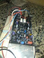
I have an older ver.pcb 1.2
This version use Latterals as drivers for BJT.
As i had most of parts in home,i did not resist to assemble this.
Using the design values bias was zero.
I placed a 1k resistor parallel to R27=910ohm
This version use Latterals as drivers for BJT.
As i had most of parts in home,i did not resist to assemble this.
Using the design values bias was zero.
I placed a 1k resistor parallel to R27=910ohm
Attachments
Last edited:
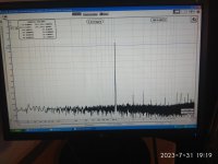
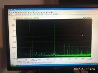
Amplifier is death silent,as you can see on the grapf.
Sound is awaysome BUT up to 10v RMS.
Power supply is +/-45v.
Increacing volume even farther,distortion becomes huge 5-10%.
Please any sugestion?
I have an mp3 recording ,using an UMIK1 micropfone and the audacity software.
Room acoustic is terrible but i hope that you can hear amplifier character.
Sound is awaysome BUT up to 10v RMS.
Power supply is +/-45v.
Increacing volume even farther,distortion becomes huge 5-10%.
Please any sugestion?
I have an mp3 recording ,using an UMIK1 micropfone and the audacity software.
Room acoustic is terrible but i hope that you can hear amplifier character.
Attachments
Last edited:
That actually makes sense. Both feedback and the ODNF circuit would be trying to correct the error in the output at the same time but the feedback circuit would be attenuating the output as well causing the ODNF circuit to try to boost the output. I wonder if Valery added the feedback expecting to use one or the other?
My feeld is that this was his goal.
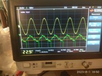
1) 20vRMS dummy load 7 Ohm
2) 3.8vRMS dummy load 7 Ohm
1) 20vRMS dummy load 7 Ohm
2) 3.8vRMS dummy load 7 Ohm
Attachments

Last edited:
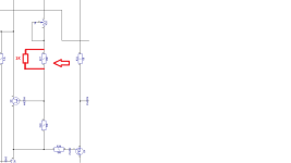
Resuming,using the printed circuit ver.1.2 we have 3 different options.
1 usege of the error correction circuit.Install U1,U2 and the periferals.NOT install R40,C21.
2 usege of the negative feedback network.Install R40,C21.NOT install U1,U2
3 without feedback,NOT install NOITHER U1,U2 NOT R40,C21.Connect TP2 to TP3.
I will post THD measurements for 3nd option soon.
1 usege of the error correction circuit.Install U1,U2 and the periferals.NOT install R40,C21.
2 usege of the negative feedback network.Install R40,C21.NOT install U1,U2
3 without feedback,NOT install NOITHER U1,U2 NOT R40,C21.Connect TP2 to TP3.
I will post THD measurements for 3nd option soon.
Is there any progress in substituting the FETs? I‘d really like to try an amp like this as my next project. But the FETs are a small stopper…It's tough to find genuine fets for these amps! I'd like to do a lower power version of the AX3 amp. It's mostly SMT but uses easy to get parts.
Version 1.32 boards are the latest, but the circuits are the same on all of the 1.3, just updates for parts fitment.
I've been playing for a few years with the AX3 version of the amp whenever time permitted, but was never really happy with the way it operated. It seemed to work okay but something always bothered me about it, but I couldn't figure out what it was. Another builder assembled a set of boards and was seeing some odd behavior in his build, so I've dug back into this one.
I had noticed some very peculiar operation of the ODNF circuit, but by this time Valery had passed away so I need to figure this one out on my own. A few weeks ago I discovered the output stage itself seemed to be unstable. I think this was due to the way it was layed out. I'm in the process of designing a new layout with a few enhancements that Valery wanted to try. If it works out the design should be possible to scale back to more civilized power output levels. We had more input stage designs in the works as well.
I had noticed some very peculiar operation of the ODNF circuit, but by this time Valery had passed away so I need to figure this one out on my own. A few weeks ago I discovered the output stage itself seemed to be unstable. I think this was due to the way it was layed out. I'm in the process of designing a new layout with a few enhancements that Valery wanted to try. If it works out the design should be possible to scale back to more civilized power output levels. We had more input stage designs in the works as well.
- Home
- Amplifiers
- Solid State
- No-global-loop amplification