Hi
I like to know how to use this simple topology without negative feedback.
In other circuits use complementary pair in the input to avoid the DC output, for the simple circuit below, what is the simplest way to avoid the DC output, when negative feedback is removed?
Thanks
I like to know how to use this simple topology without negative feedback.
In other circuits use complementary pair in the input to avoid the DC output, for the simple circuit below, what is the simplest way to avoid the DC output, when negative feedback is removed?
Thanks
Attachments
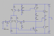
You can replace emitter degeneration resistors (R2 and R3) in the differential pair with a trimpot, connecting its wiper to the current source (Q3); this would allow you to adjust DC offset.
However, open loop gain will be high enough to make precise balancing difficult, and the result unstable. This amp without NFB is likely to be impractical, much as an op amp without NFB.
However, open loop gain will be high enough to make precise balancing difficult, and the result unstable. This amp without NFB is likely to be impractical, much as an op amp without NFB.
How are you going to select the total gain if you eliminate the feedback?
Placing a voltage divider, generally difference between the bases of differential pair is 5mV-30mV, depends on the gain of the VAS.
You can replace emitter degeneration resistors (R2 and R3) in the differential pair with a trimpot, connecting its wiper to the current source (Q3); this would allow you to adjust DC offset.
However, open loop gain will be high enough to make precise balancing difficult, and the result unstable. This amp without NFB is likely to be impractical, much as an op amp without NFB.
DC I have is half the source (15V), I need another transistor to compensate, but I do not know how is the circuit!
Is this for simulation purposes? If yes, make R21 a very low value (.001 Ohms) and C4 a very high value. You can then run your AC sims to get an idea of th eopen loop response.
If you want to build a low or ZGFB amp, then you can try heavy degeneration of the input devices and/or loading VAS to reduce the loop gain. A third method is to tap off the feedback signal from th e VAS rather than th eoutput, but this leaves you with no feedback top correct the cross over distoprtion, unless of course you are planning to run it heavily class A. Of course, you can use any combination of th e above as well (e.g. heavy degen of th e LTP and take f/back off the VAS).
If you want to build a low or ZGFB amp, then you can try heavy degeneration of the input devices and/or loading VAS to reduce the loop gain. A third method is to tap off the feedback signal from th e VAS rather than th eoutput, but this leaves you with no feedback top correct the cross over distoprtion, unless of course you are planning to run it heavily class A. Of course, you can use any combination of th e above as well (e.g. heavy degen of th e LTP and take f/back off the VAS).
Is this for simulation purposes? If yes, make R21 a very low value (.001 Ohms) and C4 a very high value. You can then run your AC sims to get an idea of th eopen loop response.
Yes is for simulation, this will increase the gain and had to use two voltage dividers. It is used in opamps
If you want to build a low or ZGFB amp, then you can try heavy degeneration of the input devices and/or loading VAS to reduce the loop gain. A third method is to tap off the feedback signal from th e VAS rather than th eoutput, but this leaves you with no feedback top correct the cross over distoprtion, unless of course you are planning to run it heavily class A. Of course, you can use any combination of th e above as well (e.g. heavy degen of th e LTP and take f/back off the VAS).
I'm trying to do is one pre-amp in class A, +- 4V RMS. I want to remove the negative feedback because not is necessary!
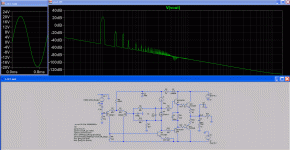
Distortion in 20KHz (with feedback)
Harmonic Frequency Fourier Normalized Phase Normalized
Number [Hz] Component Component [degree] Phase [deg]
1 2.000e+04 5.500e+00 1.000e+00 -1.00° 0.00°
2 4.000e+04 8.877e-06 1.614e-06 -119.72° -118.73°
3 6.000e+04 1.169e-06 2.126e-07 -141.78° -140.79°
4 8.000e+04 1.533e-07 2.787e-08 176.90° 177.90°
5 1.000e+05 3.605e-08 6.555e-09 167.56° 168.55°
6 1.200e+05 3.098e-08 5.633e-09 -170.17° -169.18°
7 1.400e+05 1.221e-08 2.221e-09 -155.21° -154.21°
8 1.600e+05 2.014e-08 3.662e-09 166.43° 167.43°
9 1.800e+05 2.153e-08 3.916e-09 171.56° 172.56°
Total Harmonic Distortion: 0.000163%
No wonder you have low distortion-figures as NFB might be somewhere in the +40db region.
It will be easier if you do a Diamond output stage with a servo. Crossover-distortion will not be a problem as long as you stay in Class-A. Check this out:
http://www.andiha.no/articles/audio/cascfig/sch01.gif
Cascode Power Amplifier
It will be easier if you do a Diamond output stage with a servo. Crossover-distortion will not be a problem as long as you stay in Class-A. Check this out:
http://www.andiha.no/articles/audio/cascfig/sch01.gif
Cascode Power Amplifier
No wonder you have low distortion-figures as NFB might be somewhere in the +40db region.
It will be easier if you do a Diamond output stage with a servo. Crossover-distortion will not be a problem as long as you stay in Class-A. Check this out:
http://www.andiha.no/articles/audio/cascfig/sch01.gif
Cascode Power Amplifier
Negative feedback is 36 dB, so what the distortion in open-loop is <0,01%.
the circuit is the blameless without power TRs output.
With VAS balanced, I had already seen, here an example:
http://users.ece.gatech.edu/mleach/papers/tcir/tcir.pdf
But would like a solution to blameless.
the circuit is the blameless without power TRs output.
QUOTE]
I would call it a LIN...
Douglas Self didn t invent nothing in that matter, yet, a lot
of people name this topology with his "trade marks"..
The original 1955 Harry C Lin amp used singleton input, SE VAS and PNP germanium quasi output stage with Sziklai npn driver.
If you want to build the amp without feedback, then to be strictly correct you must eschew interstage feedback, so only local feedback is acceptable..... this is really quite difficult.
As Bonsai suggests, it is best done with lashes of emitter degen on the LTP, lots of degen on the VAS, and some pretty stiff loading or feedback on the VAS collector. If the output stage is not operating in Class A, crossover could be an issue with no global feedback.
Interstage feedback between VAS collector and the LTP - the same RRC network transposed from output back to the VAS collector, and thence to fb node - is a better suggestion, however, as it will also reduce source impedance driving the output stage, always a good thing.
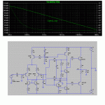
I have done a suitable Class AB zero global fb amp in the attachment, with simulation. It uses lashes of local feedback, and then adds interstage feedback from VAS back to LTP. It is possible to cut OLG to about 30dB with even more local and no interstage, but the results are not as good. As you can see, H2 is around -48dB, not very impressive. However, if you build this circuit you will be quite surprised......
Hugh

If you want to build the amp without feedback, then to be strictly correct you must eschew interstage feedback, so only local feedback is acceptable..... this is really quite difficult.
As Bonsai suggests, it is best done with lashes of emitter degen on the LTP, lots of degen on the VAS, and some pretty stiff loading or feedback on the VAS collector. If the output stage is not operating in Class A, crossover could be an issue with no global feedback.
Interstage feedback between VAS collector and the LTP - the same RRC network transposed from output back to the VAS collector, and thence to fb node - is a better suggestion, however, as it will also reduce source impedance driving the output stage, always a good thing.
I have done a suitable Class AB zero global fb amp in the attachment, with simulation. It uses lashes of local feedback, and then adds interstage feedback from VAS back to LTP. It is possible to cut OLG to about 30dB with even more local and no interstage, but the results are not as good. As you can see, H2 is around -48dB, not very impressive. However, if you build this circuit you will be quite surprised......
Hugh
Last edited:
Thanks for posting the circuit AKSA, but it seems that this circuit still uses NFB and must be compensated for not oscillate.
Distortion 20KHz - 4,2V RMS/300 Ohms
Harmonic Frequency Fourier Normalized Phase Normalized
Number [Hz] Component Component [degree] Phase [deg]
1 2.000e+04 5.979e+00 1.000e+00 -1.10° 0.00°
2 4.000e+04 1.028e-05 1.720e-06 88.78° 89.88°
3 6.000e+04 9.518e-06 1.592e-06 58.31° 59.40°
4 8.000e+04 3.768e-07 6.302e-08 175.33° 176.43°
5 1.000e+05 2.624e-07 4.389e-08 -102.73° -101.64°
6 1.200e+05 1.743e-08 2.915e-09 -179.00° -177.90°
7 1.400e+05 3.553e-08 5.943e-09 157.71° 158.80°
8 1.600e+05 2.494e-08 4.171e-09 -173.01° -171.91°
9 1.800e+05 7.452e-09 1.246e-09 -92.17° -91.08°
Total Harmonic Distortion: 0.000234%
Attachments
Zero Global Feedback
Try this one!
THD 1.19% at 1KHz, +20dB, Av of just below 50, zero global feedback, no compensation, stable. It clips early on the negative half cycle around -29V due to the heavy VAS degeneration.
Most of this distortion is H2/H3/H4, H5 is -83dB.
It would have very poor damping factor, and sound tubelike. The difficulty is keeping gain low; tricks like current mirrors make it more difficult. The network you see at the inverting input is for offset control; the amp operates open loop.
Hugh
Attachments
Hi
I like to know how to use this simple topology without negative feedback.
In other circuits use complementary pair in the input to avoid the DC output, for the simple circuit below, what is the simplest way to avoid the DC output, when negative feedback is removed?
Thanks
Negative feedback is your friend.
Cheers,
Bob
I agree emphatically. It is almost impossible to do a competent audio power amp without negative feedback. It has been given a bad rap by a dubious, ill-informed press.
Like so much of engineering, more of this means less of that. Look at the distortion figures of this amp.... and it won't even swing rail to rail.
Even if you only use interstage feedback, you still need feedback.
Like so much of engineering, more of this means less of that. Look at the distortion figures of this amp.... and it won't even swing rail to rail.
Even if you only use interstage feedback, you still need feedback.
You can probably adjust the DC offset with r10, but it will be touchy (small adjustments).
With no global feedback what kind of THD and FR do you get?
And it would be better to reduce overall gain by reducing the VAS gain with local feedback than with a divider.
The global feedback also helps keep the FR flat, without it a lot of amps are LP Filters in the audio freqs. Why dont you try an LTP as the vas, then you can set the gain with emitter degeneration and probably reduce THD.
I believe so. Can't quite figure the transconductance relationship with the complementary LTP input stage, but I note it's buffered with an EF and uses astonishingly high degeneration - 2K, huge. I'm guessing transconductance must be close to unity, in fact.
- Status
- Not open for further replies.
- Home
- Amplifiers
- Solid State
- No feedback amp