First have a measure of the DC voltage on C520 as shown here. The voltage at this point is the control voltage for the FET's and should be a positive voltage.
The actual voltage you see should be one half of the value of the supply rail produced by regulator Q501 and that looks like it will be in the positive 20 to 24 volt region. It will be one half because of the two 150k resistors forming a simple voltage divider.
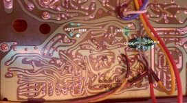
Hi. I have located R517, R518 and C519, C520 but I'm having difficulty locating the point where the measurement should be taken. The circuit drawing, I find confusing😕
I have taken a photo of the board and highlighted the positions with the hope that you can point out to me the exact position.
Re C519 and C520 I had these so I've renewed them.
Attachments
Working off pictures is never easy tbh...
The top of R517 and R518 (where they connect together) in your picture is the correct point. Anywhere on that piece of print or the component leads going to that print will do. Probably easiest and safest to measure to one of the 150k resistor legs on the top of the board.
The top of R517 and R518 (where they connect together) in your picture is the correct point. Anywhere on that piece of print or the component leads going to that print will do. Probably easiest and safest to measure to one of the 150k resistor legs on the top of the board.
Working off pictures is never easy tbh...
The top of R517 and R518 (where they connect together) in your picture is the correct point. Anywhere on that piece of print or the component leads going to that print will do. Probably easiest and safest to measure to one of the 150k resistor legs on the top of the board.
I'm reading 17v
That voltage sounds OK and would certainly bias the FET's fully on.
Two possibilities...
1/ My theory of what has been happening is incorrect and the problem lies elsewhere.
2/ The problem is intermittent and at this moment the voltage (and amp) are all working correctly.
Given the nature of faults like this I would certainly replace those two electrolytics.
Two possibilities...
1/ My theory of what has been happening is incorrect and the problem lies elsewhere.
2/ The problem is intermittent and at this moment the voltage (and amp) are all working correctly.
Given the nature of faults like this I would certainly replace those two electrolytics.
That voltage sounds OK and would certainly bias the FET's fully on.
Two possibilities...
1/ My theory of what has been happening is incorrect and the problem lies elsewhere.
2/ The problem is intermittent and at this moment the voltage (and amp) are all working correctly.
Given the nature of faults like this I would certainly replace those two electrolytics.
Ok, no worries. Given that we know that when the shorts are removed there will be distortion on the left channel, should I leave them in place?
@mooly
post 6# "This type of fault takes minutes to trace with a scope and signal generator or signal source such as a test CD or MP3 test tone file."
how difficult is it to trace a fault like this just using a multi-meter ???
gaz
post 6# "This type of fault takes minutes to trace with a scope and signal generator or signal source such as a test CD or MP3 test tone file."
how difficult is it to trace a fault like this just using a multi-meter ???
gaz
It is a lot more difficult because you are having to interpret individual results using unsuitable test gear and then having to figure out whether the reading you see is correct or not with reference to the circuit.
The scope is the essential diagnostic tool for pretty much all servicing work.
The scope is the essential diagnostic tool for pretty much all servicing work.
- Home
- Amplifiers
- Solid State
- No bass sound