Guess no one could figure out the mystery tubes in post #53 and #54.
For the record:
A: 6JK5 beam triode, main clue was the 1400V horiz. axis range
C: 19 DHT triode, clue being the DHT and very small current scale
D: and F: 6GF7 dissimilar triodes, limited # of dissimilars to pick from
G:G2:G3: 38HE7 power beam pentode combo with a damper diode, the low Rp of the pentode
curves gives it away. Notice how nice the triode configured curves are.
Probably the best 16 Watt triode around for the $0.35 it cost, or even for $1.
Last edited:
Guess no one could figure out the mystery tubes in post #53 and #54.
For the record:
A: 6JK5 beam triode, main clue was the 1400V horiz. axis range
C: 19 DHT triode, clue being the DHT and very small current scale
D: and F: 6GF7 dissimilar triodes, limited # of dissimilars to pick from
G:G2:G3: 38HE7 power beam pentode combo with a damper diode, the low Rp of the pentode
curves gives it away. Notice how nice the triode configured curves are.
Probably the best 16 Watt triode around for the $0.35 it cost, or even for $1.
The only curve that looked familiar to me was "D" which reminds me a lot of a 12AY7. That would have been my guess but it was 1/2 of a dissimilar...
Smoking-amp, this thread which delved into Schade vs. triode mode discussion has made me wonder: could you pretty pretty please post a comparison of some pentode (take your pick, one of those mentioned in that topic would be awesome) using same range settings for both triode and feedback (Schade) modes of operation, together with actual schematic (values) used ? 🙂

I'd really like to see results of real life tube side by side (straight triode mode and Schade), with actual schematic (values) so that it could be easily replicated.
Can you post your schematic or LTspice file ?
Can you post your schematic or LTspice file ?
Think back, I showed a Schaded IGBT atop 5V4GA. Calling the top portion a "Mu Starver".
Cause my thinking then it was a linear amp starving a vacuum diode to produce curves...
My complaint that it was still too darn linear, and didn't lean over to the right like a real
triode! Which led to the discussion with Smoking, where he proposed an average of triode
paths with slightly different cutoff caused the leanover... Then I go on to sim dissimilar
Mu Starvers in parallel to see what happens? Need at least four to fake realistic curves.
http://www.diyaudio.com/forums/tubes-valves/122766-se-diode.html
Can you post your schematic or LTspice file ?
Will do together with the pentode-sim! Just PM me with your E-mail address. Will just refine it somewhat tonight when I get home from work.
I also recall abusing current mirror to make small vacuum diode appear big.
Which common triode has two extra diodes that nobody ever puts to use?
Schottky, 6L6, and diode strapped MOSFET have square law. Possibly more
useful than x^1.5 when-if'n you might want to shape a smooth AB crossing.
Maybe some remote cutoff types are suitable too.
Which common triode has two extra diodes that nobody ever puts to use?
Schottky, 6L6, and diode strapped MOSFET have square law. Possibly more
useful than x^1.5 when-if'n you might want to shape a smooth AB crossing.
Maybe some remote cutoff types are suitable too.
Last edited:
Which common triode has two extra diodes that nobody ever puts to use?
There are plenty to choose from. Anything that was ever used in the 1st audio amp / detector / agc section of an AM radio including the AA5 variants.
6AT6, 6AV6, 6AQ6 and the 12 volt flavors. 7 pin miniature
6SQ7, 6Q7, 6R7, and the 12 volt flavors. Octal
7K7, and a few that I can't remember. Loktal
There were 1 and 2 volt versions for the battery tube radios, and space charge versions for car radios, then there were versions designed for FM radios, and TV sets too. The 6BN8 was the one I remember.
"Smoking-amp, this thread which delved into Schade vs. triode mode discussion has made me wonder: could you pretty pretty please post a comparison of some pentode (take your pick, one of those mentioned in that topic would be awesome) using same range settings for both triode and feedback (Schade) modes of operation, together with actual schematic (values) used ?"
I have the curve tracer apart for mods still. I finished adding in grid current curve tracing, but I still need to upgrade the grid stepper voltage supply for g2 stepping. When I get it all back together I'll do some Schade versus trioded pentode curves. There was a curve traced Schaded Mosfet curve set earlier in this thread:
http://www.diyaudio.com/forums/tubes-valves/159892-nice-triode-4.html#post2062625
edit: OH, I forgot, that one cheated a little bit by using a thermionic diode in the source lead of the Mosfet.
Last edited:
Awesome, I'm already looking forward to it ! Please post accompanying circuit values (resistors and the load) when you do.
I got a pair of 6HV5 today by mistake...
Maybe it can be Schaded to reason?
But plate voltage will be stoopid high.
Not sure what made me think this was
a low voltage, high current pentode?
But its a high voltage beam triode...
Mu=300? Go figure...
Maybe it can be Schaded to reason?
But plate voltage will be stoopid high.
Not sure what made me think this was
a low voltage, high current pentode?
But its a high voltage beam triode...
Mu=300? Go figure...
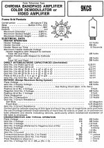
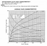
Does each cell voltage and current value is the number?Lets see what 9KC6 and 6LE8 look like in triode mode:
Post #48?
I don't have the data available any more, but probably something like 5 or 10 mA/div vertical and 50V/div horizontal.
I don't have the data available any more, but probably something like 5 or 10 mA/div vertical and 50V/div horizontal.
Again, I don't have the data anymore. But from looking at the datasheets I would guess around 0.5 V/step for the 9KC6 and 1 V/step for the 6LE8.
6LE8 datasheet:
http://frank.pocnet.net/sheets/135/6/6LE8.pdf
9KC6 datasheet in the 1968 Sylvania Receiving Tubes Technical Manual.
6LE8 datasheet:
http://frank.pocnet.net/sheets/135/6/6LE8.pdf
9KC6 datasheet in the 1968 Sylvania Receiving Tubes Technical Manual.
Attachments
Last edited:
- Status
- Not open for further replies.
- Home
- Amplifiers
- Tubes / Valves
- Nice triode