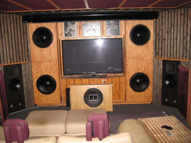
I just finished some cabinet building where Acoustic Elegance TD12M + Beyma’s TPL 150H shall replace existing LCR speakers (Altec Lansing 604-8K) in my listening room / home theater. For the low frequencies 4 pcs of AEs 18” PB18 H+ and 4 pcs of their 15” SPB 15 are already installed in the room as a double bass array (sometimes also called CABS).
For small room acoustics, absorbers, diffusers, etc, I have picked up quite a lot over the years but when it comes to filter theories and electronics, I feel I know next to nothing. I have lended out a dbx 482 active filter (never used by me yet) to a friend but will take it back soon and hook it up. Of course I don’t want to blow those expensive Beymas the first thing I do … 😱 😡 So, a first advice regarding choosing value for a protective capacitor for the TPL 150H would be much appreciated! 🙂 Crossover frequencies will probably be 110 Hz between the subs and the TD12 M and somewhere 1300 to 1600 Hz from the TD12 M to the TPL 150H.
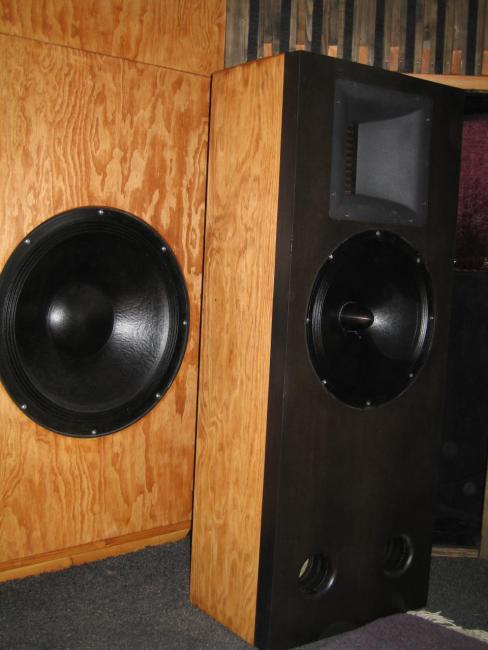
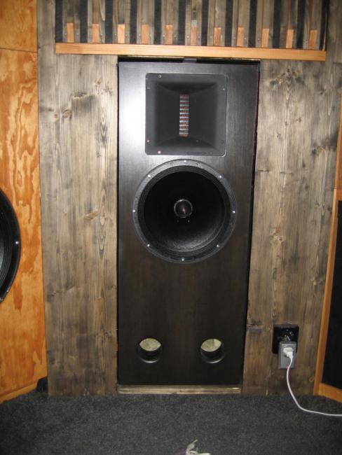
In the pictures the new black cabinets are flush mounted in a baffle kind of wall and look like ported ones. Actually, they will be used as sealed. There are 3 internal sealed compartments. Net volume for the TD12 M compartment is 18,5 L / 0,65 ft³ giving a virtual cabinet volume of between 18,8 to 22 L depending on the amount of filling (according to simulation in Unibox). The lower ported section works only as a sealed off integrated speaker stand to get the center of the TPL 150H at correct height (900 mm). In case I move, it may also be good to easily switch over to ported ones as current subs cannot be brought along. I have a whole lot of building pictures and theories behind it to share if that is of interest.
3 pictures of the Altecs 604-8K to be replaced, the back wall and a measurement of ETC and T60 for the "old setup".
For small room acoustics, absorbers, diffusers, etc, I have picked up quite a lot over the years but when it comes to filter theories and electronics, I feel I know next to nothing. I have lended out a dbx 482 active filter (never used by me yet) to a friend but will take it back soon and hook it up. Of course I don’t want to blow those expensive Beymas the first thing I do … 😱 😡 So, a first advice regarding choosing value for a protective capacitor for the TPL 150H would be much appreciated! 🙂 Crossover frequencies will probably be 110 Hz between the subs and the TD12 M and somewhere 1300 to 1600 Hz from the TD12 M to the TPL 150H.
In the pictures the new black cabinets are flush mounted in a baffle kind of wall and look like ported ones. Actually, they will be used as sealed. There are 3 internal sealed compartments. Net volume for the TD12 M compartment is 18,5 L / 0,65 ft³ giving a virtual cabinet volume of between 18,8 to 22 L depending on the amount of filling (according to simulation in Unibox). The lower ported section works only as a sealed off integrated speaker stand to get the center of the TPL 150H at correct height (900 mm). In case I move, it may also be good to easily switch over to ported ones as current subs cannot be brought along. I have a whole lot of building pictures and theories behind it to share if that is of interest.
3 pictures of the Altecs 604-8K to be replaced, the back wall and a measurement of ETC and T60 for the "old setup".
Attachments

Last edited:
Hi Adhoc,
For a basic introduction to crossovers, please see here.
For an introduction to the process of analysis you'll need to complete to design filters yourself, please see below:
http://www.diyaudio.com/forums/multi-way/288141-omnimic-far-field-xsim-dats-v2-success.html
If you can make it through all that, and get driver measurements, including distance, you'll find lots here who will help you.
There's also a sticky thread at the top of the forum about crossover design without measurements. I'm not a fan of that approach (at least not in the 21st century) but it's there.
Good luck!
Best,
Erik
Discussion: Have you compared your TD12M midrange in sealed vs. ported box alignments?
I have TD12M in a sealed box with bracing which tapers the rear volume to reduce resonances. For a 3-way design, the transient response with a sealed-box midrange is superior to a ported box alignment.
TD12M sealed: 0.75cuft for Fsc = 112Hz. Easy to complete LR4 to the woofers. 112Hz = 120" wavelength = 30" quarter-wave = good integration to adjacent woofers.
Ported box F3= 70Hz does not seem necessary with good quality adjacent woofers.
Did you consider a 3-way design for each angled side wall speaker box?
----------------
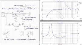
1) The TPL-150H is almost a pure 4.9-ohm resistor, and this allows good accuracy with a textbook LR4 passive circuit. Since the TPL-150H can handle 80W, most passive crossovers designs do not add a protection capacitor(50uF) beyond the high-pass crossover capacitors. (see example Xover)
2) At the crossover frequency, the TPL-150H 80-degree horizontal polar pattern should match the "early beaming" 80-degree polar of the TD12M, which occurs around 1500Hz.
3) You need to make local measurements for a quality crossover, but since your TD12M are built into a wall, you can start with "large baffle" box simulation plots to estimate passive crossover parts costs.
I have TD12M in a sealed box with bracing which tapers the rear volume to reduce resonances. For a 3-way design, the transient response with a sealed-box midrange is superior to a ported box alignment.
TD12M sealed: 0.75cuft for Fsc = 112Hz. Easy to complete LR4 to the woofers. 112Hz = 120" wavelength = 30" quarter-wave = good integration to adjacent woofers.
Ported box F3= 70Hz does not seem necessary with good quality adjacent woofers.
Did you consider a 3-way design for each angled side wall speaker box?
----------------
1) The TPL-150H is almost a pure 4.9-ohm resistor, and this allows good accuracy with a textbook LR4 passive circuit. Since the TPL-150H can handle 80W, most passive crossovers designs do not add a protection capacitor(50uF) beyond the high-pass crossover capacitors. (see example Xover)
2) At the crossover frequency, the TPL-150H 80-degree horizontal polar pattern should match the "early beaming" 80-degree polar of the TD12M, which occurs around 1500Hz.
3) You need to make local measurements for a quality crossover, but since your TD12M are built into a wall, you can start with "large baffle" box simulation plots to estimate passive crossover parts costs.
Attachments
Last edited:
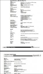
Thanks for chiming in. Weather is too unpredictable at this time of the year to bring cabinets outside for measurements. So, at this stage I am merely pondering a suitable value of a protective capacitor for the TPL 150H, to be placed between power amp and the TPL. -Told you, I am no good with electronics … 🙄 I am not planning for passive filters as the dbx 482 offers a lot of crossover types, slopes and presets so the chain will be: source -> dbx 482 -> power amp -> capacitor -> TPL 150H. (See the picture for a condensation of the technical parameters on the active filter).
The discussion: I have only simulated the response of the TD 12Ms as sealed and ported (in Unibox) and see little reason to use the LCRs as ported speakers. If I move to another place later on, I can then open up the sealed off compartments inside the cabinet and get a ported speaker. As ported, the cabinets are now tuned to roughly 60 Hz. Qtc of the sealed version falls slightly below 0,7. 0,6-0,68 or so, depending on amount of filling. I gather Qtc will rise a bit with temperature when music is on, so it should be a good compromise to plan for a “starting” Qtc a bit lower than 0,707.
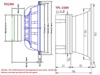
The LCR speakers are planned to be used as sealed 2 ways with supporting front subs in mono, wired in parallell + series for a total of 8 Ohm. The subs at the back wall also in mono but time delayed and out of phase versus the front subs, to suppress length modes in the room. Distance to the front subs will fall within ¼ wave length crossed at 110 Hz. C-c distance between TD12 M and TPL 150H is 282 mm. Baffle width of the new speakers are 392 mm / 15,43”and width of the grey “doghouse” where they are placed is about 860 mm / 34”. The gap between speaker and “doghouse” opening is 6 mm / ¼” on each side and should probably not produce any baffle step problems with the speakers flush mounted. The "doghouse" opens up backwards at a 15 degree angle so the speaker angle versus listening position can be adjusted. Width of the front subs are 630 mm / 24,8”.
I did not use tapered bracing to reduce resonances as you did LineSource. Instead common 90 degree bracing and constrained layer damping with MS polymer for baffle and back piece. To further reduce any cabinet resonances I will check out how well viton o-rings dampen between basket and baffle and also between screws and basket. (Checked up some NASA studies and Viton was shown to be better at damping vibrations than most elastomers in the region 100 Hz and up to treble at room temperature.) The cabinets weigh in at exactly 45 kg / 99 lbs each and have 5 vibrations dampers (feet) @ 9 kg for optimal loading, giving an “own” resonance of 14 Hz. The vibration dampers should then totally isolate vibrations to and from cabinet from 14 Hz x (root 2) = 20 Hz and upwards.
The discussion: I have only simulated the response of the TD 12Ms as sealed and ported (in Unibox) and see little reason to use the LCRs as ported speakers. If I move to another place later on, I can then open up the sealed off compartments inside the cabinet and get a ported speaker. As ported, the cabinets are now tuned to roughly 60 Hz. Qtc of the sealed version falls slightly below 0,7. 0,6-0,68 or so, depending on amount of filling. I gather Qtc will rise a bit with temperature when music is on, so it should be a good compromise to plan for a “starting” Qtc a bit lower than 0,707.
The LCR speakers are planned to be used as sealed 2 ways with supporting front subs in mono, wired in parallell + series for a total of 8 Ohm. The subs at the back wall also in mono but time delayed and out of phase versus the front subs, to suppress length modes in the room. Distance to the front subs will fall within ¼ wave length crossed at 110 Hz. C-c distance between TD12 M and TPL 150H is 282 mm. Baffle width of the new speakers are 392 mm / 15,43”and width of the grey “doghouse” where they are placed is about 860 mm / 34”. The gap between speaker and “doghouse” opening is 6 mm / ¼” on each side and should probably not produce any baffle step problems with the speakers flush mounted. The "doghouse" opens up backwards at a 15 degree angle so the speaker angle versus listening position can be adjusted. Width of the front subs are 630 mm / 24,8”.
I did not use tapered bracing to reduce resonances as you did LineSource. Instead common 90 degree bracing and constrained layer damping with MS polymer for baffle and back piece. To further reduce any cabinet resonances I will check out how well viton o-rings dampen between basket and baffle and also between screws and basket. (Checked up some NASA studies and Viton was shown to be better at damping vibrations than most elastomers in the region 100 Hz and up to treble at room temperature.) The cabinets weigh in at exactly 45 kg / 99 lbs each and have 5 vibrations dampers (feet) @ 9 kg for optimal loading, giving an “own” resonance of 14 Hz. The vibration dampers should then totally isolate vibrations to and from cabinet from 14 Hz x (root 2) = 20 Hz and upwards.
Attachments
...snip The vibration dampers should then totally isolate vibrations to and from cabinet from 14 Hz x (root 2) = 20 Hz and upwards.
EDIT: The sentence should of course be: The vibration dampers should then start to isolate vibrations to and from cabinet from 14 Hz x (root 2) = 20 Hz and upwards and totally isolate at frequencies handled by the TD12 M.
Take a read through the thread I sent again, no need for outside measurements. 🙂
Just need the right software. Either OmniMic which does blends for you, or Room EQ Wizard with the Bagby approach.
Best,
Erik
Just need the right software. Either OmniMic which does blends for you, or Room EQ Wizard with the Bagby approach.
Best,
Erik
I did some further digging on protective capacitor and came across an old technical bulletin from Altec Lansing: http://alteclansingunofficial.nlenet.net/publications/techletters/TL_205.pdf
LineSource; Thanks, 'didn't notice your suggestion at first. 50uF for about 1500/2=750 Hz / 5 ohm seems spot on versus Altec's larger diagram.
LineSource; Thanks, 'didn't notice your suggestion at first. 50uF for about 1500/2=750 Hz / 5 ohm seems spot on versus Altec's larger diagram.
The LCR speakers are planned to be used as sealed 2 ways with supporting front subs in mono, wired in parallell + series for a total of 8 Ohm. The subs at the back wall also in mono but time delayed and out of phase versus the front subs, to suppress length modes in the room. Distance to the front subs will fall within ¼ wave length crossed at 110 Hz. C-c distance between TD12 M and TPL 150H is 282 mm.
From the research I have read, the physical position of a woofer can be identified down to 60Hz for percussion transients and 80Hz for long tones.
Your present setup would probably best integrate by using doghouse ported TD12M and a 60-70Hz crossover to the swam of mono room woofers. BUT I think you would get the best sound with stereo 3-ways in each side doghouse (TPL-150H -crossed- LR4 at 1500Hz to sealed TD12M -crossed- LR4 at 110Hz to sealed/equalized 18") -SUPPORTED BY- LR4 at 60Hz to the room woofers
Since you are running the TD12M in a sealed alignment with a 110Hz bass crossover, I think you will want to experiment with stereo front bass,
---- and also experiment with turning the top two front woofers off to mimic a doghouse 3-way,
---- and also experiment with stereo crossing the top two woofers in at 60Hz.
===========
I also think you should get other opinions before any experiments.
I came across a picture you published LineSource, a cabinet with TD12 M and tapered bracing towards the back piece, I presume that’s your build (?). (‘Been doing quite a bit of digging on the site actually.)
For front and back wall subs I need to go with active filter / DSP as there should be a time delay between them to get the theory of the double bass array to work out also in practice. It is exactly 700 cm between them, so to “kill” the backwall reflection of the incoming frontal wave and reduce length modes: About 7/343 = roughly 20,4 ms delay + reversed phase for the back wall subs. (7 m requires too long a delay for the miniDSP to work for those who considers it.)
I might consider a passive filter between TD12 M and the TPL 150H Beyma though. Thanks for the filter suggestion you included. 🙂 Soldering it together should not be a problem. My ignorance lies in filter design and choice of components. When you write “You need to make local measurements for a quality crossover”, -what substantiates the “quality crossover”(?). The design itself, sure. But how important are the tolerances, +/- 2, 5 or 10% on the components to get that “quality crossover” as prices change quite a bit between a +/- 2 and a +/- 10% tolerance. Anyone care to elaborate?
I may be able to make those local measurements but the next step … 😕 What component change / choice to make to get a possible improvement? That’s a reason why an active filter seems attractive to me. (I might be totally wrong there.)
Edit: I wrote this before I read your post #8, -time for some time with the lady now ...
Last edited:
Thanks for those suggestions, much appreciated. It is possible to check them out as I had them in mind when I remodeled the room from one with superchunk corners with speakers in front, to the baffle wall / doghouse front of today.
Speaker cabling was pre drawn for separate driving of each AE sub or as stereo pairs in series or parallel or as a mono array of all 4 in series, parallel or series + parallel. The dbx 482 has a number of presets, so I will probably check them out versus each other sooner or later. I cannot put an 18”:er for a 3 way inside the doghouse itself though, as I read one of the suggestions. The front wall of the doghouse is 132 mm / 5,2” thick and to saw up the 400 mm wide opening, eh … too much work.
A double bass array with front and back wall subs should in theory be fed the same mono signal to work out well. If it works “OK” also with stereo subs, I don’t know yet.
(The front subs from AE, PB 18H+ are the same as their TD18 H+ but with a dust cap instead of phase plug. According to John Janovic at AE they should be clean and suitable up to about 500 Hz, where there is a starting break up from the dust cap.)
DSPs should allow you to eaily set up front stereo 3-way experiment.
Your bottom 18" front woofers are physically quarter-wave close enough to the doghouse TD12M to integrate as the woofer in a unified 3-way speaker: LR4 around 110Hz with the TD12M. SO, one simple experiment is to turn off the front top ceiling 18" woofers to remove any confusion, and wire the bottom 18" woofer with the TD12M as one unified 3-way. This bottom 18" woofer can either use a port for deep bass, or use electronic equalization for deep(20Hz) bass. 3-way L+R Stereo speakers. You want to cover as low freq as possible with the 18" woof.
If this sounds "great", you can next experiment with summing in the top Left and top right 18" woofers as STEREO LR4 60Hz deep bass addtions to smooth long wavelength room modes. (60Hz = 225" wavelength).
If this sounds "great", you can next experiment with summing in the rear woofers at 60Hz with the best time+phase+freq equalization. I would experiment with STEREO rear woofers first, then MONO. There are stereo vs. mono deep bass debates on the forum....I favor stereo for improved bass transients.
=============
Passive crossover
LR4 is steep enough to avoid "resonances" on TD12M above 1500Hz, and "strain" on TPL150 below 1500Hz.
Inductors are 18-AWG air core
Capacitors are 200V film
4ohm Resistor = 10watt
0.33mH = 0.3 ohm $6.50
1.5mH = 0.67ohm $12.50
1.3mH = 0.57ohm $11.50
0.68mH = 0.36ohm $7.30
Attachments
OT... Dream Big, even in a normal living room
The Tweek Geek BMF-1 speaker has started a discussion on putting several big speakers in modest size boxes. High efficiency T+M supported by high-watts DSP equalized woofers in a living room friendly box. Stylish home theater?
The Tweek Geek BMF-1 speaker has started a discussion on putting several big speakers in modest size boxes. High efficiency T+M supported by high-watts DSP equalized woofers in a living room friendly box. Stylish home theater?
Attachments
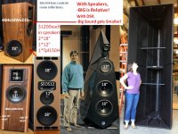
Well, what about that! Han Solo captured together with Darth Vader in the same picture! 🙂
I’m very grateful for your suggestions on passive filter. They will sure save me time, mistakes and a loooong learning curve if I take that route instead of an all active filter. Your idea with 3 way + 2 supporting upper front subs is interesting and worth checking up. Thanks!
Perhaps I should have inserted more info / pictures in the first post but too much of it sometimes hide the questions and result in no feedback. I did consider vented subs but 18” low tuned subs would have been unpractical, requiring large diameters and very long ports and the boxes are only about 300 mm / 12 inch deep … Not possible with front ports, only side ports going into the slot absorber compartments above and below the TV. –No fun! 🙁
I also had to consider the room itself, position of the subs versus surrounding surfaces, baffle size and possible room gain. A basement bunker with all surfaces concrete 200-500 mm / 8-20” thick is not easy to tame and avoid boominess. I made some simulation on baffle size, surrounding surfaces and possible room gain with Jeff Bagbys program. A sealed cabinet with low Qtc and its natural drop off and combined with possible room and pressure gain could lessen boominess problems. I choose to “oversize” the sealed cabinets and they ended up as 174 L / 6,15 ft³ net volume per element (element and bracing installed and prior to stuffing). Qtc should end up at around 0,35. As far as I understand, a low Qtc is better to start with than a higher one, if one wants to use Linkwitz transform and EQ up the lowest frequencies. More to learn there … Lowest length mode for me is at 22 Hz and pressurizing gain should start somewhere below that. The room itself is sealed off very well, has double solid wooden and steel doors with double rubber seals around etc.
Room response simulation together with baffle size, from Bagbys program
Front subs simulation from Unibox, 1, 2 and 4 subs, separate, as pairs and as quads. The drop off combined with the room gain should hopefully result in a fairly flat response down to very low frequencies.
The sub cabinets are actually some stripped down absorber modules which I increased the depth of. (A combination of limp mass + resistive with some front slats in a binary maximum length sequence.) That module contraption is glued onto the concrete wall behind. So not possible to dismantle which required some "creative thinking" to make them into speaker cabinets.
Stripped down to the rubber sheeting (limp mass)

10 cm / 4” added side wall depth + some glued on bracing
New baffle, 22 mm / 7/8” high density particle board + 14 mm birch ply rings inside + some further plywood pieces were the basket screws go. The baffle had to be screwed + glued on as clamps couldn’t be used.
4 mm plywood / veneer glued on and stuffing and speaker cables in place.
I’m very grateful for your suggestions on passive filter. They will sure save me time, mistakes and a loooong learning curve if I take that route instead of an all active filter. Your idea with 3 way + 2 supporting upper front subs is interesting and worth checking up. Thanks!
Perhaps I should have inserted more info / pictures in the first post but too much of it sometimes hide the questions and result in no feedback. I did consider vented subs but 18” low tuned subs would have been unpractical, requiring large diameters and very long ports and the boxes are only about 300 mm / 12 inch deep … Not possible with front ports, only side ports going into the slot absorber compartments above and below the TV. –No fun! 🙁
I also had to consider the room itself, position of the subs versus surrounding surfaces, baffle size and possible room gain. A basement bunker with all surfaces concrete 200-500 mm / 8-20” thick is not easy to tame and avoid boominess. I made some simulation on baffle size, surrounding surfaces and possible room gain with Jeff Bagbys program. A sealed cabinet with low Qtc and its natural drop off and combined with possible room and pressure gain could lessen boominess problems. I choose to “oversize” the sealed cabinets and they ended up as 174 L / 6,15 ft³ net volume per element (element and bracing installed and prior to stuffing). Qtc should end up at around 0,35. As far as I understand, a low Qtc is better to start with than a higher one, if one wants to use Linkwitz transform and EQ up the lowest frequencies. More to learn there … Lowest length mode for me is at 22 Hz and pressurizing gain should start somewhere below that. The room itself is sealed off very well, has double solid wooden and steel doors with double rubber seals around etc.
Room response simulation together with baffle size, from Bagbys program
Front subs simulation from Unibox, 1, 2 and 4 subs, separate, as pairs and as quads. The drop off combined with the room gain should hopefully result in a fairly flat response down to very low frequencies.
The sub cabinets are actually some stripped down absorber modules which I increased the depth of. (A combination of limp mass + resistive with some front slats in a binary maximum length sequence.) That module contraption is glued onto the concrete wall behind. So not possible to dismantle which required some "creative thinking" to make them into speaker cabinets.
Stripped down to the rubber sheeting (limp mass)
10 cm / 4” added side wall depth + some glued on bracing
New baffle, 22 mm / 7/8” high density particle board + 14 mm birch ply rings inside + some further plywood pieces were the basket screws go. The baffle had to be screwed + glued on as clamps couldn’t be used.
4 mm plywood / veneer glued on and stuffing and speaker cables in place.
Last edited:
Progress is slow but it is there. One thing at a time … And questions pop up.
Lately I hooked up the TD12 M in an empty cabinet in series with a 100 ohm resistor and tone generator to the amp to check up at which frequency the voltage would peak. Checked it from 150 Hz and downwards in 10 Hz increments to 50 Hz, then narrowed in with 1 Hz increments and found it to be at 106-106,5 Hz, this should also correspond to the Fb, system tuning frequency and resistance peak in diagrams.
The measured 106 Hz was a bit of surprise as the Unibox simulation with empty 18,5 L cabinet indicated Fb to 110,9 Hz with Qtc 0,733. Simulation in Unibox have 4 options for damping: no fill, minimal, walls covered and heavy fill. The more damping, the more the cabinets virtual volume increases, at the same time Fb shall decrease in Hz and Qtc go down as well. With heavy filling in Unibox, the acoustic volume “felt” by driver goes up to from 18,5 to 22,4 L, the Fb goes down from 110,9 to 102,4 Hz and the Qtc changes from 0,733 to 0,600. At least according to Unibox simulations.
In the Unibox simulation a series resistance of 0,3 ohm for a 11 m long 1,5 mm² speaker cable was added, Re for the driver was measured to 7,0 ohm (instead of 6,6 ohm in manufacturers specs.) The voltage meter used isn’t laboratory grade but should be decent enough (?). Resistance at room temperature for 11 m speaker cable = 2x11 m back and forth with 1,5 mm² should be 0,266 ohm for a “several strand” wire, slightly more for “multiple fine strand” wire. As the voltage meter showed 0,3 ohm, -good enough I think.
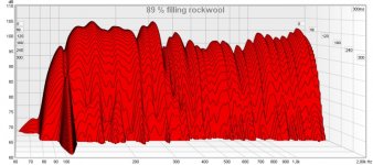
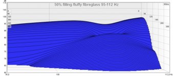
The measurement for max voltage and corresponding frequency was to check for optimal amount of damping of the cabinet . Added damping gives a lowered voltage at the found original Fb frequency, stop putting in more when voltage starts to increase again. 6 versions were tried, with fiberglass Isover Piano and rockwool Flexibatts, airflow resistivity 5 kPa and 15 kPa respectively. Starting value with empty box at 106 Hz was 103,8 mV, end value 68,7 mV, with roughly 89% filled, mostly Flexibatts along sides and in the middle with the fluffier Piano closest to driver.
Now to the question … The waterfall in REW show a fairly long tail that stands out at exactly 106,5 Hz. It dies away at 240 ms, all other higher and lower frequencies dies away at a fairly straight line of about 120 ms. This goes both for a roughly 50% filled box, mostly the Piano and also for roughly 89% filled with mostly Flexibatts. Zoomed in closely between 95-112 Hz, there seem to be no difference between the 2 fillings and none of them show a decreased tuning frequency for a larger virtual volume down to about 102 Hz from the Unibox simulation. I have ruled out room modes as microphone was moved diagonally in the room from 1,00 m up to 3,16 m, measured with a laser device so errors should only be about 5 mm in height and width, next to nothing length wise. So, the long tail at 106,5 Hz should come from the box tuning bouncing out through the cone, that’s’ my guess. But it should be lower in frequency, so where is my reasoning wrong? Is waterfall measurements completely wrong to use in this case and why doesn’t a simulated lowered tuning show up when zoomed in so closely?
(I apologize for perhaps too much text, but to avoid some proposals on where I've gone wrong , details could be good to know beforehand.)
Edit: The "hair cross" in REW was moved to max value in the pictures, for all 3 at 106,5 Hz (it doesn't show up in the pictures)
Lately I hooked up the TD12 M in an empty cabinet in series with a 100 ohm resistor and tone generator to the amp to check up at which frequency the voltage would peak. Checked it from 150 Hz and downwards in 10 Hz increments to 50 Hz, then narrowed in with 1 Hz increments and found it to be at 106-106,5 Hz, this should also correspond to the Fb, system tuning frequency and resistance peak in diagrams.
The measured 106 Hz was a bit of surprise as the Unibox simulation with empty 18,5 L cabinet indicated Fb to 110,9 Hz with Qtc 0,733. Simulation in Unibox have 4 options for damping: no fill, minimal, walls covered and heavy fill. The more damping, the more the cabinets virtual volume increases, at the same time Fb shall decrease in Hz and Qtc go down as well. With heavy filling in Unibox, the acoustic volume “felt” by driver goes up to from 18,5 to 22,4 L, the Fb goes down from 110,9 to 102,4 Hz and the Qtc changes from 0,733 to 0,600. At least according to Unibox simulations.
In the Unibox simulation a series resistance of 0,3 ohm for a 11 m long 1,5 mm² speaker cable was added, Re for the driver was measured to 7,0 ohm (instead of 6,6 ohm in manufacturers specs.) The voltage meter used isn’t laboratory grade but should be decent enough (?). Resistance at room temperature for 11 m speaker cable = 2x11 m back and forth with 1,5 mm² should be 0,266 ohm for a “several strand” wire, slightly more for “multiple fine strand” wire. As the voltage meter showed 0,3 ohm, -good enough I think.
The measurement for max voltage and corresponding frequency was to check for optimal amount of damping of the cabinet . Added damping gives a lowered voltage at the found original Fb frequency, stop putting in more when voltage starts to increase again. 6 versions were tried, with fiberglass Isover Piano and rockwool Flexibatts, airflow resistivity 5 kPa and 15 kPa respectively. Starting value with empty box at 106 Hz was 103,8 mV, end value 68,7 mV, with roughly 89% filled, mostly Flexibatts along sides and in the middle with the fluffier Piano closest to driver.
Now to the question … The waterfall in REW show a fairly long tail that stands out at exactly 106,5 Hz. It dies away at 240 ms, all other higher and lower frequencies dies away at a fairly straight line of about 120 ms. This goes both for a roughly 50% filled box, mostly the Piano and also for roughly 89% filled with mostly Flexibatts. Zoomed in closely between 95-112 Hz, there seem to be no difference between the 2 fillings and none of them show a decreased tuning frequency for a larger virtual volume down to about 102 Hz from the Unibox simulation. I have ruled out room modes as microphone was moved diagonally in the room from 1,00 m up to 3,16 m, measured with a laser device so errors should only be about 5 mm in height and width, next to nothing length wise. So, the long tail at 106,5 Hz should come from the box tuning bouncing out through the cone, that’s’ my guess. But it should be lower in frequency, so where is my reasoning wrong? Is waterfall measurements completely wrong to use in this case and why doesn’t a simulated lowered tuning show up when zoomed in so closely?
(I apologize for perhaps too much text, but to avoid some proposals on where I've gone wrong , details could be good to know beforehand.)
Edit: The "hair cross" in REW was moved to max value in the pictures, for all 3 at 106,5 Hz (it doesn't show up in the pictures)
Attachments

Last edited:
FYI...
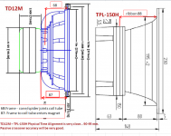
1) The physical time alignment between the TD12M and TPL-150H is very close (~5mm), which helps keep soundstage accuracy with a passive crossover. If you make delay measurements with your drivers, you could decide to put a small bevel cut adjustment on the baffle for closer timing.
2) For the TD12M passive crossover network, the thicker AWG15 inductor wire gauge is a good upgade if you plan on long sessions at >100watts. The TPL-150H is rated 80W, so the lower cost AWG18 is adequate.
The Devil is in the details.
Attachments
Thanks for that 🙂. I hadn't given the wire gauge much thought really.
You are quite right there, - the Devil is in the details. The "devil chasing" is a reason why the progress isn't at formula 1-speed exactly... I have inserted into your picture the measurements I made before I started with the cabinets. For the TPL 150H it is 88 mm from the backside of the horn frame to where the ribbon is. For TD12 M it is 87 mm from the backside of the metal basket to where the coil enters the magnet and 68 mm from the frame to the place where coil tube joints with spider and cone. I am not really sure which of those figures, 87 or 68 mm, one should see as important for a physical alignement. Any suggestions (?), I am not sure here and I have come across some papers that acoustical center varies with frequency.
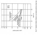
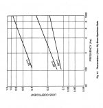
Another “devil chasing”: The gasket which comes with the TD12 M is more or less only for looks, a plasticized rubber thing, actually too hard to offer optimal sealing. (John Janovitz at AE says the same thing, it offers good looks but is not the best gasket.) So I scrapped it and have / is for fastening of the basket been checking out 2 versions of EPDM foam gaskets + wooden screws. This will give a rather firm, stiff connection so vibrations from the driver are likely to be transmitted to the wooden cabinet. –No good. The connection I will use is a more “floating” one with M6 machine screws going into slightly oversized holes in the cabinet together with a viton o-ring between wood and the basket frame. The M6 nuts + washers inside cabinet will also have viton o-rings for sealing. Reason for viton: Viton has a high loss factor and a low rebound compared in the frequency range of interest compared to other elastomers like EPDM, nitril, silicone, etc so vibrations taken up by the rubber will to a much larger degree be transformed into heat instead of given back as vibrations to the system slightly time delayed. (The diagrams are from a NASA report, in the second diagram "deg C" has been inserted instead of, I believe correctly, "deg F".)
I don’t know if these theories can actually be measured and shown with the simple gear I have, but why not go for a solution which ought to give some improvements.
You are quite right there, - the Devil is in the details. The "devil chasing" is a reason why the progress isn't at formula 1-speed exactly... I have inserted into your picture the measurements I made before I started with the cabinets. For the TPL 150H it is 88 mm from the backside of the horn frame to where the ribbon is. For TD12 M it is 87 mm from the backside of the metal basket to where the coil enters the magnet and 68 mm from the frame to the place where coil tube joints with spider and cone. I am not really sure which of those figures, 87 or 68 mm, one should see as important for a physical alignement. Any suggestions (?), I am not sure here and I have come across some papers that acoustical center varies with frequency.
Another “devil chasing”: The gasket which comes with the TD12 M is more or less only for looks, a plasticized rubber thing, actually too hard to offer optimal sealing. (John Janovitz at AE says the same thing, it offers good looks but is not the best gasket.) So I scrapped it and have / is for fastening of the basket been checking out 2 versions of EPDM foam gaskets + wooden screws. This will give a rather firm, stiff connection so vibrations from the driver are likely to be transmitted to the wooden cabinet. –No good. The connection I will use is a more “floating” one with M6 machine screws going into slightly oversized holes in the cabinet together with a viton o-ring between wood and the basket frame. The M6 nuts + washers inside cabinet will also have viton o-rings for sealing. Reason for viton: Viton has a high loss factor and a low rebound compared in the frequency range of interest compared to other elastomers like EPDM, nitril, silicone, etc so vibrations taken up by the rubber will to a much larger degree be transformed into heat instead of given back as vibrations to the system slightly time delayed. (The diagrams are from a NASA report, in the second diagram "deg C" has been inserted instead of, I believe correctly, "deg F".)
I don’t know if these theories can actually be measured and shown with the simple gear I have, but why not go for a solution which ought to give some improvements.
Attachments
Last edited:
You have a passion for understanding what makes a great speaker.
You can drive a square wave to each speaker and use your mic + measurement tools to record and compare delays.
Some invert the square wave to one driver, and physically move one driver until the "best null" is heard(measured) at the common listening position.
=========
Most ruler measurements are done to the center of the pole piece. A few mm of imperfection is accepted since the equal-delay between two drivers changes slightly as listeners move around the room.
Well, back again. Speaker building was more or less put on ice during summer, as some renovation of the house was given priority. –A wardrobe … (!), even though ladies in the house prefer to call it a walk in closet. There’s room for at least 400 pair of shoes, make up mirrors etc, so they should be satisfied. 🙄
John Janowitz at AE asked if I had a building thread in English for the drivers I bought, so I might just turn this thread into one. As it progresses, I’ll run into issues where advices from you knowledgeable guys would be welcomed (active filters, do and do nots).
Here goes: The room is a concrete bunker, all surfaces concrete, mainly used for music but also as home theater with 58” plasma TV and 110” screen. Half the height is below ground level in a basement, 7,86 x 4,19 x 2,18-2,25 m. A heaven for troublesome room modes in other words 😱 ...
When we bought the house the previous owner had integrated a new concrete bunker to the old house (1929). It was meant to be a garage but never came further than an empty concrete shell full of junk, no flooring, no internal fixed up walls, no electricity except a lone fluorescent bulb hanging from a nail in a corner. Except for the low height, perfect really for me, as I could start from scratch. One big reason for the house purchase.
It took some planning time to figure out what should and could be done to overcome foreseeable acoustical problems in the bunker.
1) Optimizing / best compromise of angels versus both stereo listening and a large screen for HT at LP was the first to work out.
2) Treatment along long walls was chosen as 4” equivalent of Owen Cornings 705, as I wanted to keep as much width as possible. 703 with its lower gas flow resistance is usually the preferred choice. That is, if you can spare about 15-30 cm. I couldn’t / didn't want to and the OC 705 is better when depth / volume is in shortage. The OC 705 was covered with a thinner outer layer of fluffy glass wool and DIY plywood copies of RPGs curved ternary BAD panels. 4000+ holes in each diffuser of 2,4x1,2 m (8’x2’), phew ... BAD panels were chosen instead of QRDs as you can sit closer to them. (The more common QRDs give lobing problems if you sit close to them.) Under the BAD panels limp mass absorbers, 7 x 0,6 m (20' x 2'), were built versus lowest width mode. Limp mass absorber = rubber sheeting of suitable weight per area unit versus the sealed air gap behind the rubber sheeting. Above the BADs some slot absorbers were built, also functioning for hiding cabling to speakers and AC-voltage.
3) Front wall got their limp mass absorbers versus lowest room mode. In front of the rubber sheeting, regular resistive absorbers of rockwool behind cloth and wooden slats according to a binary non repeatable series (to give back some of the mids and highs and not deaden the room). Some slot absorbers above and below the TV were built versus 3rd length mode.
4) Back wall got a curved vertical 40 cm deep BAD, H 2 x W 1 m, at the center, on each side a 30 cm deep 3D diffuser H 2 x W 0,8 m (volumetric diffuser as they are also called, geometry build up according to Golomb Ruler). In the back corners more BADs, 26 cm deep and from floor to ceiling and more limp mass absorbers.
5) A ceiling cloud above and in front of LP, 15 cm thick with medium density rock wool, 2,6x1,6 m (8,5’ x 5,25’) to kill ceiling reflections from front speakers.
6) 2 air locks, with 2 solid wood /steel doors in each, 20-40 cm apart and with double rubber sealings, into the house and out to the garden.
7) All visible cracks and drilled holes were sealed up with expanding polyuretan foam and covered over with flexible acrylic.
8) All acoustical fixes were built in modules of 60 or 120 cm width (2’-4’), so they could be easily rebuilt or replaced with something else later on.
9) 4 distributed subs were chosen, 2 up front at ¼ width distance from side walls and 2 at the back wall, also at ¼ width distance from side walls, -to kill the first 3 width modes even out length modes a bit.
10) 4 surround speakers per L+R surround channel are used from 18 degrees in front of LP and evenly distributed towards the backwall.
All in all this worked out pretty well and few modifications had to be made. Some free standing reflectors/absorbers were built and added so first order reflections from side walls were redirected towards the back wall and some Haas kickers there. After the modifications the ETC showed -20 to -30 dB of reflections versus direct sound, with a late wanted reflection of -12 dB at about 28 ms. T60 / Shroeder integral measured in REW show about 24 ms from about 63 Hz and up to 20 kHz, so the room is on the quiet side but not dead sounding, bass response feels really even in the room and also "fast" with low QTC sealed sub cabinets.
The Altec 604-8K drivers I have used as LCRs were bought as NOS about 10 years ago. I have always liked those Altecs but they need large enclosures (mine are 180L / 7,5 ft³). I decided to try out some smaller cabinets with AEs TD12 M together with Beyma’s TPL 150H, to be flush mounted into a kind of baffle wall and at the same time make the room more of a RFZ room (an RPG design proposal , Reflection Free Zone). With the rebuild I can also hook up a double bass array with 4 of AEs PB 18H+ at the front and 4 of AEs SPB 15 at the back wall. Time will show if I shall put the old Altecs into retirement and keep the newer driver designs.
‘ Will add some pictures later on but now it’s long past bed time.
John Janowitz at AE asked if I had a building thread in English for the drivers I bought, so I might just turn this thread into one. As it progresses, I’ll run into issues where advices from you knowledgeable guys would be welcomed (active filters, do and do nots).
Here goes: The room is a concrete bunker, all surfaces concrete, mainly used for music but also as home theater with 58” plasma TV and 110” screen. Half the height is below ground level in a basement, 7,86 x 4,19 x 2,18-2,25 m. A heaven for troublesome room modes in other words 😱 ...
When we bought the house the previous owner had integrated a new concrete bunker to the old house (1929). It was meant to be a garage but never came further than an empty concrete shell full of junk, no flooring, no internal fixed up walls, no electricity except a lone fluorescent bulb hanging from a nail in a corner. Except for the low height, perfect really for me, as I could start from scratch. One big reason for the house purchase.
It took some planning time to figure out what should and could be done to overcome foreseeable acoustical problems in the bunker.
1) Optimizing / best compromise of angels versus both stereo listening and a large screen for HT at LP was the first to work out.
2) Treatment along long walls was chosen as 4” equivalent of Owen Cornings 705, as I wanted to keep as much width as possible. 703 with its lower gas flow resistance is usually the preferred choice. That is, if you can spare about 15-30 cm. I couldn’t / didn't want to and the OC 705 is better when depth / volume is in shortage. The OC 705 was covered with a thinner outer layer of fluffy glass wool and DIY plywood copies of RPGs curved ternary BAD panels. 4000+ holes in each diffuser of 2,4x1,2 m (8’x2’), phew
... BAD panels were chosen instead of QRDs as you can sit closer to them. (The more common QRDs give lobing problems if you sit close to them.) Under the BAD panels limp mass absorbers, 7 x 0,6 m (20' x 2'), were built versus lowest width mode. Limp mass absorber = rubber sheeting of suitable weight per area unit versus the sealed air gap behind the rubber sheeting. Above the BADs some slot absorbers were built, also functioning for hiding cabling to speakers and AC-voltage.3) Front wall got their limp mass absorbers versus lowest room mode. In front of the rubber sheeting, regular resistive absorbers of rockwool behind cloth and wooden slats according to a binary non repeatable series (to give back some of the mids and highs and not deaden the room). Some slot absorbers above and below the TV were built versus 3rd length mode.
4) Back wall got a curved vertical 40 cm deep BAD, H 2 x W 1 m, at the center, on each side a 30 cm deep 3D diffuser H 2 x W 0,8 m (volumetric diffuser as they are also called, geometry build up according to Golomb Ruler). In the back corners more BADs, 26 cm deep and from floor to ceiling and more limp mass absorbers.
5) A ceiling cloud above and in front of LP, 15 cm thick with medium density rock wool, 2,6x1,6 m (8,5’ x 5,25’) to kill ceiling reflections from front speakers.
6) 2 air locks, with 2 solid wood /steel doors in each, 20-40 cm apart and with double rubber sealings, into the house and out to the garden.
7) All visible cracks and drilled holes were sealed up with expanding polyuretan foam and covered over with flexible acrylic.
8) All acoustical fixes were built in modules of 60 or 120 cm width (2’-4’), so they could be easily rebuilt or replaced with something else later on.
9) 4 distributed subs were chosen, 2 up front at ¼ width distance from side walls and 2 at the back wall, also at ¼ width distance from side walls, -to kill the first 3 width modes even out length modes a bit.
10) 4 surround speakers per L+R surround channel are used from 18 degrees in front of LP and evenly distributed towards the backwall.
All in all this worked out pretty well and few modifications had to be made. Some free standing reflectors/absorbers were built and added so first order reflections from side walls were redirected towards the back wall and some Haas kickers there. After the modifications the ETC showed -20 to -30 dB of reflections versus direct sound, with a late wanted reflection of -12 dB at about 28 ms. T60 / Shroeder integral measured in REW show about 24 ms from about 63 Hz and up to 20 kHz, so the room is on the quiet side but not dead sounding, bass response feels really even in the room and also "fast" with low QTC sealed sub cabinets.
The Altec 604-8K drivers I have used as LCRs were bought as NOS about 10 years ago. I have always liked those Altecs but they need large enclosures (mine are 180L / 7,5 ft³). I decided to try out some smaller cabinets with AEs TD12 M together with Beyma’s TPL 150H, to be flush mounted into a kind of baffle wall and at the same time make the room more of a RFZ room (an RPG design proposal , Reflection Free Zone). With the rebuild I can also hook up a double bass array with 4 of AEs PB 18H+ at the front and 4 of AEs SPB 15 at the back wall. Time will show if I shall put the old Altecs into retirement and keep the newer driver designs.
‘ Will add some pictures later on but now it’s long past bed time.
Last edited:
A bunch of pictures, from a junk room with massive concrete walls to a finished room. I’ll let the pictures speak for themselves and skip technical stuff on why and how, unless anyone asks. From start to finished took me about 6,5 months work on weekends and a couple of hours in the evenings.


The room was from the beginning planned for best possible symmetry and I started out with about 1/2 reflective / diffusive surfaces and 1/2 absorbtive surfaces (disregarding the wall to wall carpeting). A bit of LEDE room thinking with the front 1/3 of the room absorbtive and the backwall more reflective/diffusive.
With the sub placements and the limp mass absorbers, te bass response / treatment of room modes turned out satisfactory, especially considering the concrete shell. I kind of suspected from beginning it would turn out a bit too dead in the mids and treble, some pictures over some of the resistive absorbers improved a little bit but not that much. It's quite easy to improve on mids and treble though, if one plans and prepares for it in advance. =>Modifiation 1 to follow.
Last edited:
From the 1st room layout some modifications were made. Targets for modifications, with passive means (no eq / electronics):
1) Increase the T60 with 0,1 second in mid and treble to about 0,25 ms and lowering T60 in the lower bass to hopefully the same 0,25 ms.
2) If possible, at the same time increase bass absortion.
3) Decrease amplitude of 1st order reflections from walls, ceiling, floor and “stuff” to below -20 dB, compared to direct sound.
How? Worth trying out was:
1) Partially covering the pure resistive absorbers with wooden slats in a maximum length sequence (a binary pattern), MLS, mirrored for left and right side walls to keep the room symmetry. -Should reflect more of high mids and treble, instead of being absorbed and also give some diffusion.
2) Rebuild the 2 absorbers at back wall to sealed Helmholtz ones with a BAD panel cover. Decreasing the RPGs “usual” 12,7 mm (1/2”) diameter to 10 mm should improve its low frequency absorbtion and also reflect and diffuse more of mids and high.
3) A large ceiling cloud in front of and above LP, a purely resistive absorber. Or, perhaps a BAD cloud together with some side polys.


The modifications turned out pretty well, gave a bit of a lift in mid and treble and upper bass got improved.
The diagrams below show simulations from AFMG Soundflow on what could be expected from modifying the resistive absorbers on the back wall to Helmholtz ones with a BAD panel covering having about 9% open area. The "thumb gif one" with a single curve = 190 mm resistive absorber/ rockwool at 30 kg/m³, everything of mid and treble will be absorbed, so kind of deadening the room. The diagram with two curves = the Helmholtz one. Red curve with glass wool filling with density 96 kg/m³ / gas flow resistivity 33 kPa (equivalent to OC 705), the blue curve with fluffy glass with ensity 11 kg/m³ / gas flow resistivity 6 kPa. Depth behind BAD panel = 260 mm for both curves. Obviously, if you wish to absorb bass, a fluffy wool of substantial thíckness is better suited than one with high gas flow resistivity of the same thickness. (260 mm is still on the low side, actual thickness turned out to be 300 mm.)
http://www.component.se/forum/uploads/monthly_02_2012/post-398-0-53536000-1329784393_thumb.gif

1) Increase the T60 with 0,1 second in mid and treble to about 0,25 ms and lowering T60 in the lower bass to hopefully the same 0,25 ms.
2) If possible, at the same time increase bass absortion.
3) Decrease amplitude of 1st order reflections from walls, ceiling, floor and “stuff” to below -20 dB, compared to direct sound.
How? Worth trying out was:
1) Partially covering the pure resistive absorbers with wooden slats in a maximum length sequence (a binary pattern), MLS, mirrored for left and right side walls to keep the room symmetry. -Should reflect more of high mids and treble, instead of being absorbed and also give some diffusion.
2) Rebuild the 2 absorbers at back wall to sealed Helmholtz ones with a BAD panel cover. Decreasing the RPGs “usual” 12,7 mm (1/2”) diameter to 10 mm should improve its low frequency absorbtion and also reflect and diffuse more of mids and high.
3) A large ceiling cloud in front of and above LP, a purely resistive absorber. Or, perhaps a BAD cloud together with some side polys.
The modifications turned out pretty well, gave a bit of a lift in mid and treble and upper bass got improved.
The diagrams below show simulations from AFMG Soundflow on what could be expected from modifying the resistive absorbers on the back wall to Helmholtz ones with a BAD panel covering having about 9% open area. The "thumb gif one" with a single curve = 190 mm resistive absorber/ rockwool at 30 kg/m³, everything of mid and treble will be absorbed, so kind of deadening the room. The diagram with two curves = the Helmholtz one. Red curve with glass wool filling with density 96 kg/m³ / gas flow resistivity 33 kPa (equivalent to OC 705), the blue curve with fluffy glass with ensity 11 kg/m³ / gas flow resistivity 6 kPa. Depth behind BAD panel = 260 mm for both curves. Obviously, if you wish to absorb bass, a fluffy wool of substantial thíckness is better suited than one with high gas flow resistivity of the same thickness. (260 mm is still on the low side, actual thickness turned out to be 300 mm.)
http://www.component.se/forum/uploads/monthly_02_2012/post-398-0-53536000-1329784393_thumb.gif
- Home
- Loudspeakers
- Multi-Way
- Newly built, LCRs with AE TD12 M and Beyma TPL 150H, advices welcomed