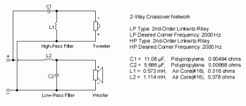
Yes, I only looked at it for a minute or two but it seems straightforward. The upper coil is in series with the woofer. The tweeter has a second order arrangement (capacitor and coil) followed by two resistors (the pot branches two ways). The tweeter is connected with reverse polarity.
i must first ask if you can measure the values, in mH, of the coils so you can source replacements?
I don't understand how you would replace the 50 ohm pot with a single fixed 25 ohm resistor. I would replace it with a variable 8 or 16 ohm L pad control.
I don't understand how you would replace the 50 ohm pot with a single fixed 25 ohm resistor. I would replace it with a variable 8 or 16 ohm L pad control.
Basically, there is no need to change the coils as their inductance and dc resistance suits Wharfedale's original purpose.
Replace the capacitor with a new non-polar (NP) electrolytic capacitor, again to suit Wharfedale's original purpose.
Replace the 50 ohm pot with an 8 or 16 ohm variable L pad control, or a new 50 ohm pot. You will find the facility to adjust the treble level useful.
Tell us where you are based if you require help in sourcing replacements.
I'd suggest pulling one of the tweeter leads then measure the resistance on both parts of the pot when it is in the position that gives you the sound you prefer.
Your crossover circuit is as in the first attachment, but without C2 in parallel with the woofer. (Ignore the component values shown.)
How to add an L pad to the tweeter is shown in the second attachment.
How to add an L pad to the tweeter is shown in the second attachment.
Attachments

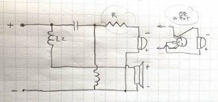
Thank you for your replies! I'll report back re. the coils. For now, I'll start with the capacitors and the L-pad. Doesn't the pod influence the signal? My plan is to find a setting on the potentiometer I like most, measure its resistance at that setting with a multimeter, and find a resistor that equals that value with a 10 Watt rating. The green wire wound resistors like Lynk should be a step up over the potentiometer. (25ohm was just my guess at the Pot is 50 Ohm). I'm attaching my version of the schematic based on what you Galu sent. Does that make sense / is this the way to wire the resistor if I would want to replace the Pot with one? *and if you say replace the pot with the pot / why 8-16 Ohm as opposed to 50?
Attachments

This might show the legs of the pot better, you have drawn them differently. You will want to measure 2-1 and 2-3 to get the two values.

I'm attaching my version of the schematic based on what you Galu sent. Does that make sense / is this the way to wire the resistor if I would want to replace the Pot with one?
Your first schematic in post #46 is correct.
However, if you want to dispense with the 50 ohm pot, and want the tweeter at maximum level, you could omit R entirely.
If the tweeter is too loud you can include R, but it need only have a low value e.g. 2 or 3 ohms - exact value to be decided by listening.
R would actually be better placed to the left of C where it won't affect the crossover frequency.
Attachments

...and if you say replace the pot with the pot / why 8-16 Ohm as opposed to 50?
You mean if I say replace the 50 ohm pot with the 8/16 ohm L pad control.
50 ohm pots were used by Wharfedale in the days before variable L pads became readily and cheaply available.
Pots do not present the constant impedance/load to the crossover that L pads do, meaning that L pads give better treble control than pots.
Details here: https://willys-hifi.com/collections/l-pad-attenuators
You would choose the mono L pad value that best matches the impedance of your tweeter.
The schematic in post #46 does not appear to be correct if I'm not mistaken. The tweeter should connect to 2 and 3, not 1 and 2.Your first schematic in post #46 is correct.
I am referring to the basic schematic on the left, which is correct.
I am disregarding the 50 ohm pot as the OP wants rid of it!
I am disregarding the 50 ohm pot as the OP wants rid of it!
Allen, I don't think it is clear to the OP why you are suggesting replacing the pot with two separate resistors.
We know how a pot works, but the OP thinks it is just a variable resistor.
We know how a pot works, but the OP thinks it is just a variable resistor.
"My plan is to find a setting on the potentiometer I like most, measure its resistance at that setting with a multimeter, and find a resistor that equals that value"
So, after reading both of your posts I'm unsure whether you're with me or not in having Zeitler overcome this misunderstanding and use two resistors?
I've already made my points in posts #41 and #48.
I've already made my points in posts #41 and #48.
It is certainly an option for Zeitler, if explained clearly to him, perhaps by relating to the physical layout in the photo of his crossover.
Referring to the attached photo, you would first disconnect the wires going to the pot, noting carefully to which terminals they went.
Then measure the resistance between the centre terminal of the pot and its upper terminal to find the appropriate value of the upper fixed resistor to put across the connecting wires instead of the pot - then measure the resistance between the centre terminal and the lower terminal to establish the value of the lower resistor to put across the connecting wires instead of the pot.
Then measure the resistance between the centre terminal of the pot and its upper terminal to find the appropriate value of the upper fixed resistor to put across the connecting wires instead of the pot - then measure the resistance between the centre terminal and the lower terminal to establish the value of the lower resistor to put across the connecting wires instead of the pot.
Attachments

Last edited:
I agree, and did that in posts #44 and #48.
I'd be inclined to keep the pot numbered 1, 2, 3 from the top down.
Secondly, I have this prepared to demonstrate how the pot is like two resistors. All three circuits here are effectively identlcal.

I'd be inclined to keep the pot numbered 1, 2, 3 from the top down.
Secondly, I have this prepared to demonstrate how the pot is like two resistors. All three circuits here are effectively identlcal.
Last edited:
I agree, and did that in posts #44 and #48.
I'm not denying that, I understood your posts, it's just that I thought Zeitler would benefit from more practical assistance.
P.S. Your image is not loading yet, but it could be a computer glitch at my end.
- Home
- Design & Build
- Parts
- Newby Question about Potentiometer Replacement in Speaker Crossover