I'm at a loose end today, so decided I'd try to quantify the impedance variation as seen by the crossover with, and without, the fixed 8 ohm resistor in place.Perhaps an attempt to keep the impedance (and therefore the crossover frequency) “more” constant.
I'm representing the tweeter itself with an 8 ohm resistance and assuming the use of the 32 ohm pot.
1. With 8 ohm resistor
(a) At full volume setting we would have 32//8//8 = 3.6 ohm
(b) At mid point of rotation we would have 16 + (16//8//8) = 19.2 ohm
2. Without 8 ohm resistor
(a) At full volume setting we would have 32//8 = 6.4 ohm
(b) At mid point of rotation we would have 16 + (16//8) = 21.3 ohm
Conclusion: The inclusion of the fixed 8 ohm resistor does not keep the impedance as seen by the crossover more constant, but it does lower it a little on average. My method and arithmetic may have to be peer reviewed though!
Maybe my wife is right, and I ought to get a life! 😀
P.S. If nothing else, my figures go to show the advantage of using a constant impedance level control! 😎
I've done some quick calculations on your series LC circuit, courtesy of my copy of 'More About Loudspeakers' by Gilbert Briggs of Wharfedale fame. 😎
Assuming 8 ohm loads, I calculate the following approximate LC figures:
To crossover at 3,000Hz: L = 0.4mH and C = 8uF
To crossover at 1,500Hz: L = 0.8mH and C = 16uF
However, your inductor appears to have 2.0mH stamped on it, so back to the drawing board!
Assuming 8 ohm loads, I calculate the following approximate LC figures:
To crossover at 3,000Hz: L = 0.4mH and C = 8uF
To crossover at 1,500Hz: L = 0.8mH and C = 16uF
However, your inductor appears to have 2.0mH stamped on it, so back to the drawing board!
Last edited:
The application that jumps to mind for me is limiting one branch of the L-Pad. ie setting a maximum series impedance.
It's a logical fit with the oddly sized L-Pad and would keep the crossover frequency more constant over the range. I still maintin that if you can get any reliable measurements out of that L-Pad then it might help recreate a usable situation. Otherwise I would be reverse engineering the function of a 32ohm L-Pad to get at least, say 3 dial positions (6 resistor values) and work out what this crossover was originally expected to see in practice.
It's a logical fit with the oddly sized L-Pad and would keep the crossover frequency more constant over the range. I still maintin that if you can get any reliable measurements out of that L-Pad then it might help recreate a usable situation. Otherwise I would be reverse engineering the function of a 32ohm L-Pad to get at least, say 3 dial positions (6 resistor values) and work out what this crossover was originally expected to see in practice.
We currently have no evidence to suggest that the level control is an L pad and not simply a potentiometer.
If Craig has an ohmmeter, I can tell him how his one remaining good L pad should measure.
32 ohm is certainly an odd value, be it L pad or potentiometer.
If Craig has an ohmmeter, I can tell him how his one remaining good L pad should measure.
32 ohm is certainly an odd value, be it L pad or potentiometer.
Last edited:
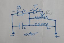
The 8 ohm resistor is connected between terminals 3 and 2 of the control.The application that jumps to mind for me is limiting one branch of the L-Pad. ie setting a maximum series impedance.
So assuming the control to be an L pad, the resistor would indeed influence the series resistance arm.
Attachments
I sincerely appreciate all your insight and guidance, particularly because much of this is well over my head. I do have an ohmmeter, so I can measure the good pot/L-pad.
You must disconnect the variable control from the circuit to make the measurements.
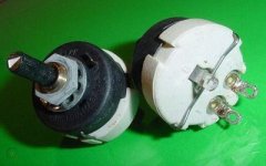
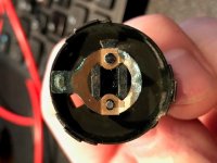
See the attachment for the way the terminals are numbered.
Measure the resistance between the centre terminal (2) and each of the outer terminals (1 and 3) in turn, while rotating the shaft of the control.
If it is an L pad, one side will vary from the 32 ohm maximum to zero ohm, while the other side will vary from zero ohm to a very high value and then infinity at full clockwise rotation.
Attachments
P.S.
Terminals 1 to 2 (the centre one) is the parallel resistor value.
Terminals 3 to 2 is the series resistor value.
Terminals 1 to 2 (the centre one) is the parallel resistor value.
Terminals 3 to 2 is the series resistor value.
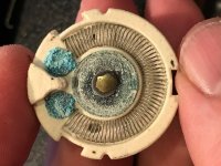
Pulled the unscathed pot/L-pad from the other crossover and measured resistance.
Probes on terminal 1 and terminal 2 with the knob all the way to the left measures 32.6 Ohms. When I turn the knob all the way to the right it measures .4 ohms.
Probes on terminal 2 and terminal 3 with the knob all the way to the left measures .3 Ohms. When I turn the knob all the way to the right it measures 32.9.
With the probes on terminal 1 and 3, the measurement is a constant 32 Ohms.
Does that make it a pot or an L-pad?
It's a simple potentiometer.
I would go ahead and use your 16 ohm AR replacements.
As to the fixed 8 ohm resistor, I also calculated its effect on a 16 ohm pot, which is minimal, and you may leave it in (or out if you wish to experiment!). 😎
I would go ahead and use your 16 ohm AR replacements.
As to the fixed 8 ohm resistor, I also calculated its effect on a 16 ohm pot, which is minimal, and you may leave it in (or out if you wish to experiment!). 😎
I tested the pots from the AR, too, but I think they are something else or damaged.
They three terminal that are marked 1, 2 and B. The B terminal is opposite the shaft.
Probes on terminals 1 and 2 result in 15.9 throughout the range. No change at all as you rotate the knob.
Probes on terminals 1 and B show an open circuit through the range. No change at all as you rotate the knob.
Probes on terminals 2 and B also show an open circuit through the range. No change at all as you rotate the knob.
All 4 of them test this way.
I'm researching!
The AR pots are Aetna-Pollak 16 ohm ceramic frame pots.
The wiper may be corroded and not making contact with the resistance wire as it turns.
If you take one apart, you can check its internal condition.
However, buying a new linear wire wound pot of a suitable resistance and a decent power handling would now seem to be the simplest way forward!
Attachments
Last edited:
Understood. You certainly hit that nail on the head.
While I have various forms of de-oxit, these are pretty far gone.
I have some 25 Ohm 5 Watt linear wire wound pots on the way.
I'll circle back when everything is back together.
Thank you very much!
While I have various forms of de-oxit, these are pretty far gone.
I have some 25 Ohm 5 Watt linear wire wound pots on the way.
I'll circle back when everything is back together.
Thank you very much!
Attachments
Thank you!
It's best to renovate those speakers as closely as possible to what the manufacturer originally intended.
The crossovers and pots may upset modern sensibilities, but it is they that give the speakers their unique period sound.
I'm looking forward to your final report. 😎
It's best to renovate those speakers as closely as possible to what the manufacturer originally intended.
The crossovers and pots may upset modern sensibilities, but it is they that give the speakers their unique period sound.
I'm looking forward to your final report. 😎
Circling back to fill in those who helped solve this problem. Again, many thanks for all your time and assistance.
While everything was apart, I re-stained the baffle because I like the drivers uncovered.
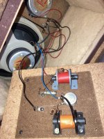
Today I reassembled the crossovers with the new pots and capacitors. The pots had to be rotated 90 degrees from there original orientation to make room for the new caps. I think they came out pretty well.
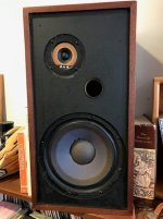
Installed the crossovers and fill and then the drivers. I used the reproduction phenolic ring tweeters instead of the original Peerless paper cones.
Once together, I went over the cabinets with some Howard's Restor-A-Finish and 000 steel wool. They came out quite nicely.
How do they sound? I still love them, but I think the phenolic ring tweeters may have been an overcompensation. The Peerless were a little too bright/harsh, the phenolics not quite efficient enough. I'm going to let everything play for a while to let the new caps and new tweeters settle in.
Time to circle back to some other oldies but goodies that need attention.
Cheers.
While everything was apart, I re-stained the baffle because I like the drivers uncovered.
Today I reassembled the crossovers with the new pots and capacitors. The pots had to be rotated 90 degrees from there original orientation to make room for the new caps. I think they came out pretty well.
Installed the crossovers and fill and then the drivers. I used the reproduction phenolic ring tweeters instead of the original Peerless paper cones.
Once together, I went over the cabinets with some Howard's Restor-A-Finish and 000 steel wool. They came out quite nicely.
How do they sound? I still love them, but I think the phenolic ring tweeters may have been an overcompensation. The Peerless were a little too bright/harsh, the phenolics not quite efficient enough. I'm going to let everything play for a while to let the new caps and new tweeters settle in.
Time to circle back to some other oldies but goodies that need attention.
Cheers.
Attachments

Neat work! 😎
You've changed three components simultaneously, and each change will have had an effect on the character of the loudspeaker.
Given time, your ears are likely to adapt to the new sound balance.
The 5W pots have the minimum power rating for the task. However, provided you don't continually play your music overly loud, this should not be a problem.
I'm new to this, but this chain looks like I found the right brains for my vintage puzzle.
I'm trying to rebuild crossover on Wharfedale W20D and I can't find the schematics. Could you please help me with transposing this photo into a schematic I could use? My goal is to replace the capacitor, coils, wiring, and get rid of the potentiometer (50 Ohm) /replace it with a solid wire resistor 25 Ohm/10W).
I'm trying to rebuild crossover on Wharfedale W20D and I can't find the schematics. Could you please help me with transposing this photo into a schematic I could use? My goal is to replace the capacitor, coils, wiring, and get rid of the potentiometer (50 Ohm) /replace it with a solid wire resistor 25 Ohm/10W).
Attachments
- Home
- Design & Build
- Parts
- Newby Question about Potentiometer Replacement in Speaker Crossover