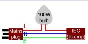
It's just a light socket and a power cord, but if you triple-check your wiring and ensure pots P1 and P2 are at zero ohms, I think you can skip the bulb tester.
The bulb tester is pretty easy. I just used this picture as a guide. I bought a bulb socket holder thingy from home depot and cut open a power cord and wired it up. A power cord has the three wires in it so when you cut it open wire the live wire into the bulb then out. I can take a photo of it later and post it to show how easy it is.
It saved me once from frying my amp and I've used it multiple times since.
It saved me once from frying my amp and I've used it multiple times since.
Attachments
Thanks, You guys have sold me on the light bulb tester. The diagram looks simple. Can someone point me to a cheap amazon bulb tester kit or step by step guide for idiots on the internet.
If you think this will not be your last amp project, (and it rarely is) you might want to invest in a variac. I found it quite valuable. Searching around, one can be found for very reasonable money.
Basically like a "throttle" for the voltage, it allows you to slowly ramp up the voltage. With a meter on the bias, no problem with burning them up if pot is open. Once the bias begin to build, you can dial it back, re adjust offset, increase voltage and so on until you get the bias you want to let it cook for a while.
In the mean time, the slow turning up of the voltage, combined with keeping an eye on other components starting to show problems or beginning to smoke of discolor....
A light bulb tester can be useful for preventing major catastrophe on first fire up of course. I find that if I build power supply first, and it measures right, I personally am ready to proceed with variac and fire up.
If something is wrong on the board, usually the voltages are not correct in the early part of fire up, and you stop, look it over, post pics here, whatever it takes to find the error. Typical errors I've made are incorrect value of resistor, small similar jfets mixed up, other small transistor in wrong place. I usually build symmetrically, so I will USUALLY have same problem on both sides.
Didnt save me on my third BA3 FE build, where I was a bit tired and over enthusiastic in that it was the third one. A power supply, which measured perfectly itself, was miss wired to the board and I dialed up to quick, voltages all wrong and I cooked the small mosfets on the FE board. Inexpensive mistake that the bulb tester probably would have caught, or maybe if I had dialed up the variac slower?
All this said, the F5 was my first Pass build and the see saw notion of adjusting the two pots during fireup was confusing for me. I found Aleph J easier by far, and M2 even more so. BA3 power amp is similar to F5 in fire up.
Works for me, just a thought.
Russellc
Last edited:
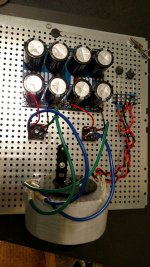
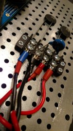
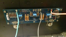
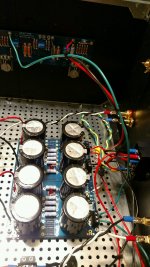
Not entirely sure about the wiring to the vishay blocks but it seems to emulate the F5 build thread although different wire colors.
Not sure what to do with the purple wire- maybe chassis ground?
1/2 way on the terminal block ...
The terminal connects in the last photo on the PCB near the star ground - what connections do these accept - perhaps the bullet connects I have in an assorted Box?
Thanks again for the info on the bulb tester. I guess I have time to explore these possible routes🙂
Attachments
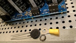

That was some unfinished work, sorry 😱
How would you apply insulation after things are soldered?
If you mean to thermistor legs, easy. Unscrew the orings loose, slide over oring end, apply heat and reattach. Use the smallest heatshrink that will fit over o ring. You can cheat a little by temporarily expanding the heatsshrink by inserting needle nose pliers in and stretching a bit.
Or, use electrical tape. Better yet, since you left plenty of length on legs, cut off oring and re do them.
Russellc
Last edited:
I'm using silicone isolation for NTC legs ; if you don't have any , go to local store , buy some 1.5 to 2.5sqmm wire with silicone isolation , and take what you need .....
PL is usually mounting them with bare legs , but they're on pcb and well away from anything , so even bent they can't touch anything critical
PL is usually mounting them with bare legs , but they're on pcb and well away from anything , so even bent they can't touch anything critical
Pass Labs.
You can click into the photos in the guide for bigger versions. Should open in new window.

You can click into the photos in the guide for bigger versions. Should open in new window.

The high res photos are in the guide. Click into them.
I think you've got it connected properly. Get out the bulb tester and give it a go!
I think you've got it connected properly. Get out the bulb tester and give it a go!
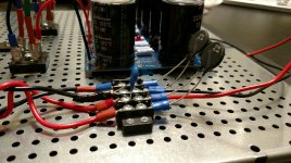
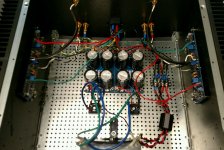
Now for the hardest part: firing it up. All 4 pots were zeroed on the multimeter. With W502 facing me right side up, it was full clockwise.
Where can I find power up and bias directions for a newbie using a cheap variac.
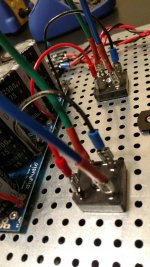
What should be done with this purple wire?
Please notice the flux capacitor in place. Now if I could only find a Delorean 😉 I
Where can I find power up and bias directions for a newbie using a cheap variac.
What should be done with this purple wire?
Please notice the flux capacitor in place. Now if I could only find a Delorean 😉 I
Attachments
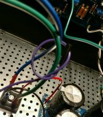
Purple wire to chassis ground.
Use a bulb tester, not a variac. The bulb tester will save you from almost all faults automatically, where the variac needs a much deeper understanding of what’s going on and what to look for and how.
Use a bulb tester, not a variac. The bulb tester will save you from almost all faults automatically, where the variac needs a much deeper understanding of what’s going on and what to look for and how.
Hi Tuberoller,
Please have a look at the few posts around here:
https://www.diyaudio.com/forums/pass-labs/335350-f5-build-11.html#post5770961
Also, please verifying the zero-ing out of P1 and P2 by actually measuring the
resistance across R5 and R6. They should be close to zero.
Dennis
Please have a look at the few posts around here:
https://www.diyaudio.com/forums/pass-labs/335350-f5-build-11.html#post5770961
Also, please verifying the zero-ing out of P1 and P2 by actually measuring the
resistance across R5 and R6. They should be close to zero.
Dennis
- Status
- Not open for further replies.
- Home
- Amplifiers
- Pass Labs
- Newbie help with F5