^^Nice work!
If the output supplies are fed by a common transformer, you might find it more prudent to fuse the primary rather than the secondaries. The reason is if only one of the secondary fuses blows, the amp is able to make a lot of DC.
If you have fuses for each power tube (a really good idea) then there is less need for a speaker protection fuse unless you plan to operate really low power speakers like vintage Lowthers.
Very encouraging. I've run into a few component supply problems with my own construction, namely the HV resistors.4 years on and no problems with my otl amp
Can you put some schematics ? this is OTL ?hello ,
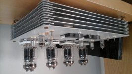
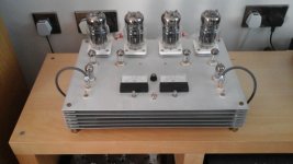
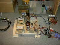
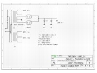
my proto to test ... not final end ...
only class A ( use one EL 509 for on way )
😉
Can you put some schematics ? this is OTL ?
hello ,
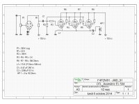
the schematic for first proto to 3 EL 504 !
😉
Attachments
Nice concept except coupling cap which can alter the sound. The firs stage what valve it is ? how does it sound ?hello ,
the schematic for first proto to 3 EL 504 !
😉
Nice concept except coupling cap which can alter the sound. The firs stage what valve it is ? how does it sound ?
Are you referring to the C2 capacitor in series with the loudspeaker, in the amplifier schematic? It is really no more, or less, in the signal path than the smoothing capacitor C2 that appears in the power supply schematic. And it is hard to avoid capacitors in the signal path in the power supply!
Chris
I know this theory and I agree. Nevertheless in practice there are limitations.Are you referring to the C2 capacitor in series with the loudspeaker, in the amplifier schematic? It is really no more, or less, in the signal path than the smoothing capacitor C2 that appears in the power supply schematic. And it is hard to avoid capacitors in the signal path in the power supply!
Chris
If you dont mind, I put a sym, what do you think about?the EL 504 or EL 509 is drived to ECC 82 😉
Attachments
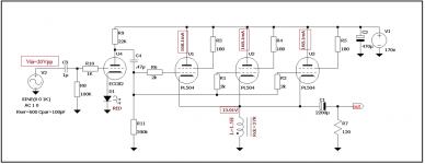
I need some advice. I am having trouble matching the high voltage resistors, R8 and R9 to a tolerance of 1%. Is it OK to put two lower voltage rating resistors at half the resistance value in series to double the effective voltage rating?
I need some advice. I am having trouble matching the high voltage resistors, R8 and R9 to a tolerance of 1%. Is it OK to put two lower voltage rating resistors at half the resistance value in series to double the effective voltage rating?
Yes you can , each 4M7 res. can be substituted with two or more series connected resistors , for example, standard values of 1M+1M+1M+1M+680K resistors combination can work there just OK ,
or combination of three standard 2M2+2M2+270K ...
Regards
Thanks Banat. I have discovered the cause of my failure to match these 4.7 MOhm resistors. The problem arose because my digital multi-meter would not hold a steady reading when trying to measure each resistor in a bandoleer of 25 5% resistors in order to get 2 pairs that were matched to 1%. The meter reading would not hold steady; it was just impossible to do the measurements.Yes you can , each 4M7 res. can be substituted with two or more series connected resistors , for example, standard values of 1M+1M+1M+1M+680K resistors combination can work there just OK ,
or combination of three standard 2M2+2M2+270K ...
Regards
My friend who is another retired sound engineer came up with the solution: he suggested that it was an RF problem, and right enough I happen to live 2 miles away from a mountain which has a large number of VHF broadcast antennas as well as some cell phone stations. He suggested connecting a 100nF capacitor across the resistors during the measurement, and lo and behold it worked. Apparently, my house is swimming in RF. It's important to let the capacitor fully charge while measuring which involves holding the meter probes on the measuring points for up to 30 seconds. I now have 2 matched pairs to 1% tolerance.
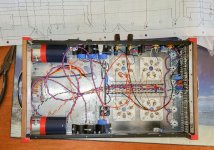
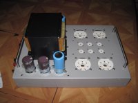
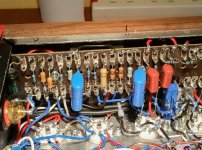
Right channel wired.
The right channel driver wiring is complete. It looks a bit untidy but I suppose that's the nature of tag-strips. RV2 L+R are accessible from the top of the chassis for adjustment.
The right channel driver wiring is complete. It looks a bit untidy but I suppose that's the nature of tag-strips. RV2 L+R are accessible from the top of the chassis for adjustment.
Attachments
Last edited:
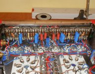
Left and Right
The left and right channel pre-amps and driver sections are wired now. There's no doubt that tag-strips are a messy business. BTW the photo was taken with my new Samsung Galaxy Note 4, with which I'm very pleased. The incredible detail is achieved by the device automatically capturing 5 or 6 different exposures and combining them into one image, all in the space of a few milliseconds.
The left and right channel pre-amps and driver sections are wired now. There's no doubt that tag-strips are a messy business. BTW the photo was taken with my new Samsung Galaxy Note 4, with which I'm very pleased. The incredible detail is achieved by the device automatically capturing 5 or 6 different exposures and combining them into one image, all in the space of a few milliseconds.
Attachments
- Home
- Amplifiers
- Tubes / Valves
- New Tim Mellows OTL project