I just questioned if you have deduced Vout from V0 in your calculation and you said you already have. I don't see it very clearly, and your 2 calculations differed by more than 2 %. So I wasn't modify it, just that after deduction it's closer to your earlier calculation. I presume you're correct!
Last edited:
No, I was only ever saying that the expression for the efficiency should be (Pi/4) * Vout/V0. That other formula I wrote down was my attempt to interpret what I thought you were suggesting, and I then went on to argue that it couldn't be right because it didn't have the right limit in the "maximal" case where Vout=V0.
Sorry if I misunderstood what you weer saying.
Chris
Sorry if I misunderstood what you weer saying.
Chris
Feedback won't affect the internal resistance at all. The proof of this is that the output power at lower impedances will be unaffected. If the internal resistance was really in fact reduced, this would not be the case.
...
No.
Well, I still yet have to fully experience it. As this time I have the sim for cathode and voltage follower based on your M60.
For the moment I would ask as if voltage follower gives more power than cathode follower in your experience. Cathode follower has lot of feedback (if not NFB) whilst voltage follower has more gain and therefore more efficient, so if you convert M60 amp to voltage follower will that give you more power and efficiency.
Actually there's no real difference in gain if the tubes are used in a Circlotron. No difference in output impedance either. We used to build the original MA-2s as "voltage follower" outputs, but other than phase inversion, there was no measurable difference between that and driving the load with the cathodes. But building the amp was a lot easier if the load is cathode driven!
...
An easy way is to calculate efficiency based on the current drawn by the amplifier. For a class B amplifier the average current drawn from the power supply is Ipeak/Pi, for 25W in 8 ohm Ipeak is 2.5A so the average current from the power supply is 2.5/3.14 ~ 0.8A.
....
Going back to efficiency, if you get 25W with 231W input efficiency is about 11%
Average current = 2.5A * 0.636 = 1.59A, according to Amplifier Efficiency.
If 1.59A, then 150*1.59=238.5-25=213.5*2=427W dissp, which one is correct?
0.8A or 1.59A?
Average current = 2.5A * 0.636 = 1.59A, according to Amplifier Efficiency.
If 1.59A, then 150*1.59=238.5-25=213.5*2=427W dissp, which one is correct?
0.8A or 1.59A?
Ok I got it, if 1.59A, then no need times 2, so just 213.5W or ~107W each tube 😎.
No, I was only ever saying that the expression for the efficiency should be (Pi/4) * Vout/V0. That other formula I wrote down was my attempt to interpret what I thought you were suggesting, and I then went on to argue that it couldn't be right because it didn't have the right limit in the "maximal" case where Vout=V0.
Sorry if I misunderstood what you weer saying.
Chris
You're correct at least agreed with this lecture. Vout is the peak voltage of the output, which is 20V-p in our case. eff=78.5*20/150=10.47%, or 238W dissp. is a little higher compared to the other calculation (214W). Thank you.
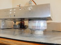
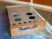
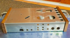
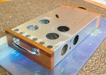
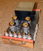
I'm mounting T2 and T3 concentrically each side of the top surface and T1 at the side of the chassis. All three transformers will be terminated on two connection blocks which sit over (under) a custom mounting plate for T2.
Attachments
Ace Hardware has them.
I'm just back from Berlin and I brought 3 "non-magnetic" bolts in my carry-on luggage. There was a small problem with security but the German police eventually OKed them for boarding. I had tested them in the bolt suppliers with a magnetic clasp on my belt and they showed no magnetism but when I used a more powerful magnet on arrival home, I found them to be about 10% as magnetic as ordinary mild steel bolts. I reckon that 10% magnetic will still fit the bill, so one of them will be used to secure the two larger concentrically mounted transformers.
Spray paint.
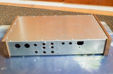
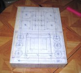
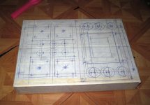
All holes are now drilled and I'm ready to spray the chassis satin black. I have noticed in the past that ordinary cheap spray paint from the hardware store is just not durable. Can anyone suggest a good brand?
All holes are now drilled and I'm ready to spray the chassis satin black. I have noticed in the past that ordinary cheap spray paint from the hardware store is just not durable. Can anyone suggest a good brand?
Attachments
Why not use aluminum furnace powder coating, such services are popular. The paint would be scratched proof and not expensive. Usually it's difficult to paint aluminum, you have to scratch the surface or it would stick properly, the coating service should be able to do surface treatment if necessary.
Last edited:
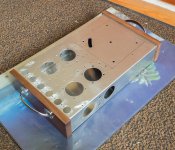
I eventually found a tough acrylic auto paint in an auto parts shop. It's called "Hycote Satin Black". The photos are of a mock-up only with protective tape temporarily on the wood. I should be in a position to start the wiring in about a week.
Attachments
A great start. I was lucky enough to have my chassis with an adhesive plastic protector already there to draw onto. I wish you luck. Whereas for me the wiring will be a walk in the park, I found all the mechanical work hard and time-consuming.
thanks, i used wide masking tapes....layout on it as you can see the tentativeness...
the chassis will be powder coated textured light grey.....
am using the 6J32 in place of the ef86, and trying to get the 6n2 in place of the 12ax7 for an all russian amp, Anatoly will like it...😉
the chassis will be powder coated textured light grey.....
am using the 6J32 in place of the ef86, and trying to get the 6n2 in place of the 12ax7 for an all russian amp, Anatoly will like it...😉
FWIW, although not as pretty, if the output tube sockets are mounted above the chassis rather than below, it appears that they will last longer before the filament connections fail. An air gap between the socket and chassis is recommended whether the socket is above or below the chassis.
Thanks for that tip. I can mount above or below. I'm just about to install them now, so I'll size the outside option first and see if the tubes stand lower than the transformer cover. It would help wiring, testing and maintenance if they are lower, as the the 3 transformers are so heavy that the amp can stand inverted on the transformer box without any extra support.
FWIW, although not as pretty, if the output tube sockets are mounted above the chassis rather than below, it appears that they will last longer before the filament connections fail. An air gap between the socket and chassis is recommended whether the socket is above or below the chassis.
i am mounting my sockets below the chassis, with a gap pf 8 to 10mm...
i will use copper strip sinks on filament socket pins to hopefully get rid of some heat...i may even use active cooling....
Assembly
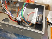
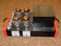
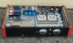
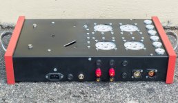
The assembly is almost done. All that remains are the 3 transformers, 2 fuse-holders and the 2 meters. I have a fuse in each of the 2 supplies for both the left and right channels, 4 in all. There is a fuse in the left and right loudspeaker outputs as well as a mains fuse, 7 fuses in total; overkill some might say but I have read all the posts on the two Mellows OTL threads and decided to be on the cautious side, particularly in the light of all that cnpope had to say about catastrophic failures.
The two long strings of capacitors for HT2 and HT4 have been combined into just two Panasonic 4,300 uF 250 Volt units (part number ECE-P2EA432HA) and all other psu capacitors are mounted on two sub plates. All connections to the tube-socket terminals will be taken to two rows of tag-strips and any associated components will be mounted there. The 4 trim-pots for the bias are accessible from the top of the chassis, so during operation there will be no need to remove the bottom cover.
Due to the weight of the two largest transformers, I had to strengthen the base underside with a 3mm alum plate and spine because of a considerable sag. Wiring will commence in the next day or so.
Attachments
- Home
- Amplifiers
- Tubes / Valves
- New Tim Mellows OTL project