Hi Matthew Morgan J,
Post #697: "... think i have figured out a solution to this by turning my 8th order idea completely upside down by making the rear chamber into my main pipe..."
It would be much easier to follow your description, and maybe to help, if you would add Hornresp reference lables to you sketches (S1/S2...Vtc...Vrc...). Also, by Hornresp convention the sound has to pass from S1 past S2 and S3, and also by S4 on its way to S5, I don't think that is the case in Post #691.
Just interested, and trying to understand.
Regards,
Hi there TB46 ,
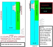
The sketches in #691 are just different ways to fold the sims in #689 ... In those examples the long section of the pipe (the one tuned low) are S1-S5 in HR, and the short section is the rear chamber, but i am finding that there are alternative ways to arrange basically the same thing in HR using the different chambers and S1-S5....David's software is totally ingenious..... Since we aren't using any taper or expansion it is all pretty flexible as long as you keep in mind that the chambers don't support driver offsets..🙂
I can color code one of the sketches for you...
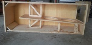
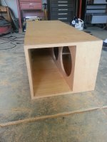
Braces in and mouth is rough cut, baffle flush cut to come after final side is in (after my 2nd driver and speakon terminals show up shipped cross country).
What's left to do in the order I plan to do it:
What's left to do in the order I plan to do it:
- Cut handle near bottom mouth
- Paint all visible interior parts of the cab and draw lines to paint final side (where visible)
- 'drill speaker wire hole and cut/install speakons near the driver end of the throat (making Absolute sure it seals)
- Install wiring to speakon's/prepping the daisy chain of the two drivers.
- Install final side
- (slight) bondo/roundover every edge, Paint External, then screw in speakon terminals, wait a while to dry
- Driver Mount/Leak/Seal test, Epoxy as needed
Attachments
Hi Matthew Morgan J,
It would be much easier to follow your description, and maybe to help, if you would add Hornresp reference lables to you sketches (S1/S2...Vtc...Vrc...)
Regards,
TB46,
Here is a color coded key 🙂
Attachments
Hi Matthew Morgan J,
Thank you for the color coded key.
Regards,
You are welcome Sir, it was no problem, MS paint is fun! 🙂
OKV ,
This is great to hear!
I would love to see some of your work, if you ever feel comfortable in doing so please share some pictures or weblinks when you can? Or if not feel free to send me something in private .. 🙂
There are some pictures on my website (Kvalsvoll Design AS) and also on my blog (kvalsvoll.blogspot.com), I think you will find pictures of the small sub there.
The subwoofers will be presented on my website.
@ Okv
Hi, i sent you a PM yesterday 😉 Very informative www & clever design work etc. Thanx for posting 🙂
*
Some nice stuff going in here, congrats to everyone involved 🙂
Hi, i sent you a PM yesterday 😉 Very informative www & clever design work etc. Thanx for posting 🙂
*
Some nice stuff going in here, congrats to everyone involved 🙂
@ Okv
Hi, i sent you a PM yesterday 😉 Very informative www & clever design work etc. Thanx for posting 🙂
*
Some nice stuff going in here, congrats to everyone involved 🙂
Thank you for the reminder, I did not notice the message.
Hornresponse does give me a warning in red on the inputs page about the sq cm area of the smaller chamber/pipe (rear chamber) being less than the driver's SD , but you can look at the diagram and see that it is only smaller by a minor degree so i am not concerned.
Hi MMJ,
Just to clarify - the caution message is simply an advisory note to the user. The accuracy of the simulation results is not adversely affected in any way.
(The Calculate button will be disabled if results are affected).
Kind regards,
David
Hi MMJ,
Just to clarify - the caution message is simply an advisory note to the user. The accuracy of the simulation results is not adversely affected in any way.
(The Calculate button will be disabled if results are affected).
Kind regards,
David
David , well that is good to hear! 🙂
So i could squeeze those chambers down even more if needed and not have to worry about the results being innacurate .... Excellent ... I don't ever remember pushing things so far as to make the "calculate" button unavailable ...
So far it looks like the ideal place for the driver offset to be located is around the middle of the small chamber for maximum bandwidth... The small chamber usually only comes out to about two feet long in most of these designs it seems (with the larger main pipe's fundamental tuned from 35hz to 40hz) so that offset is really easy to achieve and can still be achieved using two drivers spanned within the same cabinet (if they are 10" or 12" drivers).....
As I think OKV mentioned earlier in the discussion damping/filling material can be really useful in these sorts of designs, and i am seeing that stuffing the first half of the chamber (the half closer to the closed end of the small chamber) can really help to smooth out the upper response without taking away from the lower end of the response which is notable because normally the stuffing will cause some loss in the low end, but not in this case ... hmm
 ...
... Bandwidth, cab size and output all look very similar to a tapped horn (with maybe only slightly more output with the 8th order Transflex), and with zero expansion this makes for a simple build except for the need for a access panel which i don't see any way around ...
Last edited:
Sabaspeed ,
How goes on your end? Any luck on getting hold of your friend that wanted those 10S4 cabs? Your dual tapped horn looked like it was coming along nicely ...🙂
How goes on your end? Any luck on getting hold of your friend that wanted those 10S4 cabs? Your dual tapped horn looked like it was coming along nicely ...🙂
I don't ever remember pushing things so far as to make the "calculate" button unavailable ...
Hi MMJ,
Sorry, my comment was a bit misleading 🙂.
The Calculate button is disabled if an invalid configuration is specified (for example, a tapped horn with two segments).
Kind regards,
David
Sabaspeed ,
How goes on your end? Any luck on getting hold of your friend that wanted those 10S4 cabs? Your dual tapped horn looked like it was coming along nicely ...🙂
Got a hold of him, turns out I'm going to have to find another buyer. Tapped horn will be painted tomorrow or if the mail comes too late Wednesday (duratex has to ship cross country -> we need a california distributor!!!).
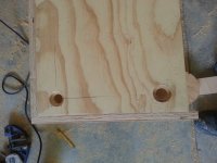
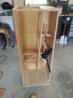
Driver 2 comes in wednesday, hardware (speakons) are supposed to arrive Tuesday (seperate shipment than duratex). Not much new to show you guys besides this really sweet routing. Note that my dad had me knock out the two stick braces due to bow issues and the one that we replaced it with is much more aptly placed, right at the point of stress, cut a little short to relieve PL pressure strain. Yes I cut those speakon recesses by hand (meaning not cnc) with a homeade jig and a not-quite-a-plunge-router. The last view is just what it will look like buttoned up, last side doesn't go on until after paint is done.
Yes that end panel is one solid piece, and I love the way it looks.
Attachments
Spent a whole day prepping with bondo, painting, last panel glueing (difficult and time consuming), Probably 10 hours split up throughout the day (dry times). Will post pictures once paint dries. Does anyone know the best way to seal the nl4mp-st speakon chassis mount connector? Those are the ones with the screw down terminals rather than the spade lugs. I realized it isn't airtight (major air leakage potential, that's what I get for being lazy and not wanting to deal with lugs/terminals that ultimately make a mess) and have been debating between PL: messy and permanent, vs Hot glue:Less pain in the neck, dries fast, removable. These are right in the throat so they need to be bulletproof. Open to ideas. I have: PL, Hot glue, some epoxy...those are the main adhesives I have at the moment.
Also, I got all my parts in, 2nd driver was "refurbished" but was in original packaging (sealed) and was better protected than the "new" driver. HMMM, I'd say buy the rest of them but shhh let me snag those first. (63.00 including shipping and no tax, I know, huge steal)
Hi sabespeed 521,
Post #714: "... the best way to seal the nl4mp-st speakon chassis mount connector?"
How about behind a corner brace in the corner where the drivers are? It will not affect the performance.
Regards,
Post #714: "... the best way to seal the nl4mp-st speakon chassis mount connector?"
How about behind a corner brace in the corner where the drivers are? It will not affect the performance.
Regards,
Hi sabespeed 521,
Post #714: "... the best way to seal the nl4mp-st speakon chassis mount connector?"
How about behind a corner brace in the corner where the drivers are? It will not affect the performance.
Regards,
Found out it wasn't hermetic after side was glued on, hence no corner piece. Also putting a corner piece there would make wiring a bit more difficult (not impossible but painful).
In the future (since i mistakenly bought 6 of these chassis connectors) I'll probably do the corner piece.
Used excessive hot glue/PL to do my best at sealing the NL4mp-st's. Will check on it tomorrow. Having a heck of a time making my own gasket for rear-mount on driver 2. Oh it's basically 1 hour from being demo-able but tomorrow is travel day so that may be a while, plus the infamous leak test could set me back a day or 1 glue period). It's fully painted now, wiring is glued in place with driver 1 (farther from mouth) is reverse polarity below deck and everything else is standard polarity (easiest way I could keep it straight).
Used excessive hot glue/PL to do my best at sealing the NL4mp-st's. Will check on it tomorrow. Having a heck of a time making my own gasket for rear-mount on driver 2. Oh it's basically 1 hour from being demo-able but tomorrow is travel day so that may be a while, plus the infamous leak test could set me back a day or 1 glue period). It's fully painted now, wiring is glued in place with driver 1 (farther from mouth) is reverse polarity below deck and everything else is standard polarity (easiest way I could keep it straight).
Feeling really bad. Severe connector and driver noise issues. Can't get the connector to work (NL4mp-st) connected directly to bypass and I get this really nasty noise at high excursion and playing upper (>65 Hz) frequencies. Kind of like a buzzing/driver rub potentially.
Uh oh ,Feeling really bad. Severe connector and driver noise issues. Can't get the connector to work (NL4mp-st) connected directly to bypass and I get this really nasty noise at high excursion and playing upper (>65 Hz) frequencies. Kind of like a buzzing/driver rub potentially.
can you tell where the buzzing noise is coming from?
Were you able to test the woofer's free-air excursion (to check for mechanical noise) before you loaded them into the box?
- Home
- Loudspeakers
- Subwoofers
- New sub design? Constricted Transflex, simple build (series tuned 6th order)