In my house it only took ~120+ dB depth charge explosions in the U-571 movie to bring the ceiling down on me. 🙁
GM
GM
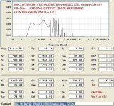
Let me know if the slightly higher compression ratio would be an issue. the expected mount pattern would be two by two (deep and tall). Definately needs baffle rings but that's besides the point -> this is one sub you only need one of.
Okay enough blabbering: see below
Oh and P.S. the reason that MMJ's standard of "doubling the inductance" from the stated value is valid is because the standard is to report it as 1khz or 20 khz inductance, which as we know a drivers inductance is very frequency dependant and almost all have ~1.5-2x the inductance in the subwoofer passband -- i.e. <100 Hz, than at the spec'ed frequency, of course the only way to get it right is an inductance curve - not too hard to measure if you have the tools.
Mr EPA mentioned the inductance curve issue here recently as well:
http://www.diyaudio.com/forums/subwoofers/261522-inductors-saddle-shape-hornresp.html
As far as compression ratio is concerned it is my understanding that up to 3:1 is considered acceptably safe as long as your cone is durable.
Anyone wanting to make a more powerful Housewrecker can use 4 swr's like so
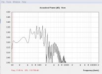
I mean 140 dB at 11 Hz after corner and typical room gain accounting for 5 dB of driver headroom , if that doesn't induce an earthquake I don't know what will.
Saba,
Thats pretty outrageous!
Music isn't going to have much content down there but it could be fun to play around with a subharmonics synthesizer with a cabinet like that, although most of the sub-synth processors i have heard sound kinda weird to me , definitely best to use those very conservatively..
Movies are of course a different story and as GM mentioned be careful because you can damage your house! 😛
When mounting one driver forward and one in reverse do you invert the phase of one or should they be in phase? Like in tb's posts a bit back. I'd like to do this because it makes reaching screws easier and heck I might as well get reduced distortion while I'm at it (assuming Push-Pull would work in this arrangement).
When mounting one driver forward and one in reverse do you invert the phase of one or should they be in phase? Like in tb's posts a bit back. I'd like to do this because it makes reaching screws easier and heck I might as well get reduced distortion while I'm at it (assuming Push-Pull would work in this arrangement).
When trying PP one driver will need to be phase reversed so that both cones are moving in the same direction at the same time, as if they were one big driver.
Mr EPA mentioned the inductance curve issue here recently as well:
http://www.diyaudio.com/forums/subwoofers/261522-inductors-saddle-shape-hornresp.html
As far as compression ratio is concerned it is my understanding that up to 3:1 is considered acceptably safe as long as your cone is durable.
Good to know. The SWR cone is quite strong, SWS is Meh strong (only seen sws in person, but swr is tuned lower and is a much heavier mmd/driver in general , read -> beefy.
Anyone wanting to make a more powerful Housewrecker can use 4 swr's like so
I mean 140 dB at 11 Hz after corner and typical room gain accounting for 5 dB of driver headroom , if that doesn't induce an earthquake I don't know what will.
Almost forgot: This is only useful in conjunction with another High power horn to cover the 35-100 range (see rest of thread).
UPDATE .... WIDE BANDWIDTH AND HIGH OUTPUT POSSIBLE-- 8TH ORDER
FULLY THRILLING AND THOUGHT-PROVOKING UPDATE! :
😱
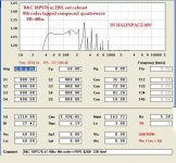
I have been doing some more work with these 8th order concepts using Hornresponse and i had suspected that using a driver with different parameters might extend the bandwidth and make this "8th order Transflex" more competitive with other popular Pro Audio bass horn designs ...
INITIAL RESULTS LOOK EXTREMELY PROMISING! (in sim at least)😀
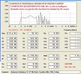
Great output and bandwidth in a relatively small package if you use drivers with high motor strength ..
Compression ratio is very low on these designs, seems like so far i am getting ratios in the range of 1.3:1 to 1.7:1 range which means that drivers are less likely to suffer from physical failures like cone folding/tearing/shredding or the distortions & power-compression losses associated with cone stress or BL insufficiency.
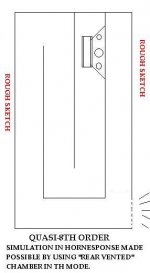
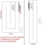
These particular sims were aiming for useable extension to 40hz keeping the cabs compact for portable PA usage ..... I am sure these sims could be fine-tuned a little further, but i just wanted to demonstrate the potential .... I also posted one additional sketch as an example of a folding option for this type of 8th order Transflex ... 🙂
note: Hornresponse does give me a warning in red on the inputs page about the sq cm area of the smaller chamber/pipe (rear chamber) being less than the driver's SD , but you can look at the diagram and see that it is only smaller by a minor degree so i am not concerned .
FULLY THRILLING AND THOUGHT-PROVOKING UPDATE! :
😱
I have been doing some more work with these 8th order concepts using Hornresponse and i had suspected that using a driver with different parameters might extend the bandwidth and make this "8th order Transflex" more competitive with other popular Pro Audio bass horn designs ...
INITIAL RESULTS LOOK EXTREMELY PROMISING! (in sim at least)😀
Great output and bandwidth in a relatively small package if you use drivers with high motor strength ..
Compression ratio is very low on these designs, seems like so far i am getting ratios in the range of 1.3:1 to 1.7:1 range which means that drivers are less likely to suffer from physical failures like cone folding/tearing/shredding or the distortions & power-compression losses associated with cone stress or BL insufficiency.
These particular sims were aiming for useable extension to 40hz keeping the cabs compact for portable PA usage ..... I am sure these sims could be fine-tuned a little further, but i just wanted to demonstrate the potential .... I also posted one additional sketch as an example of a folding option for this type of 8th order Transflex ... 🙂
note: Hornresponse does give me a warning in red on the inputs page about the sq cm area of the smaller chamber/pipe (rear chamber) being less than the driver's SD , but you can look at the diagram and see that it is only smaller by a minor degree so i am not concerned .
Attachments
-
 QUASI-8TH ORDER-ROUGH SKETCH--2 (no constrictions).JPG20.2 KB · Views: 382
 -
 18PS76-8TH-ORDER-220L-HALFSPACE-COLLAGE.JPG74.6 KB · Views: 378
 -
 4012HO-8TH-ORDER-TRANSFLEX-40hz-2CABS-HALFSPACE---COLLAGE.JPG78.9 KB · Views: 370
 -
 18TBW100-225L-8TH ORDER- TRANSFLEX-HALFSPACE 89V-HR--COLLAGE.JPG73.6 KB · Views: 374
Last edited:
Those designs are interesting, but definitely take longer to build, also it appears that access panel is a must here and that it may require 2 seeing as you need access to both sides of the driver mount... Intriguing technically though.
Ok onto the good stuff: progress update.
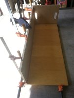
Flush cut the sides to the height of my other pieces of wood (47 7/8 for all 4 sides now)
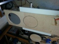
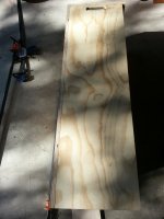
2 Glue joints done (see pics) and baffle holes cut + t-nuts in. Expecting to do corner reflectors where you see handles in the pictures and in the bottom corner for speakon connectors with (lucky i kept it around) previous speaker port material that is pre-cut to 45's and the perfect size, lucky me right?
You can see said 45 degree cut port material -- reflector material -- in the back of some of these pictures with the other spare wood.
Anyways you can tell I'm excited and it is partly due to the fact that I have access to many more clamps so these first two glue-ups (all of mine use biscuit joints) have been a breeze. Yes I am using PL premium, I am happy to say that there are 0 possible airleaks so far, you can tell I like my joints square and airtight?
Ok onto the good stuff: progress update.
Flush cut the sides to the height of my other pieces of wood (47 7/8 for all 4 sides now)
2 Glue joints done (see pics) and baffle holes cut + t-nuts in. Expecting to do corner reflectors where you see handles in the pictures and in the bottom corner for speakon connectors with (lucky i kept it around) previous speaker port material that is pre-cut to 45's and the perfect size, lucky me right?
You can see said 45 degree cut port material -- reflector material -- in the back of some of these pictures with the other spare wood.
Anyways you can tell I'm excited and it is partly due to the fact that I have access to many more clamps so these first two glue-ups (all of mine use biscuit joints) have been a breeze. Yes I am using PL premium, I am happy to say that there are 0 possible airleaks so far, you can tell I like my joints square and airtight?
Attachments

Last edited:
Those designs are interesting, but definitely take longer to build, also it appears that access panel is a must here and that it may require 2 seeing as you need access to both sides of the driver mount... Intriguing technically though.
The sketch for the 8th order Transflex shown in post #689 was a multi-fold, but it can be done as a single fold too, it just creates a cabinet with very tall & skinny aspect ratio and very small footprint so that could be desirable in some scenarios ... Only a single access panel is required as long as you run the wire internally before gluing the last parts of the box together, which is common practice anyhow with traditional designs...
I would like to be able to eliminate the need for an access panel altogether but it would require quite a large offset of the driver in the rear chamber to get it close to the mouth and i don't know if HR can sim that sort of thing (at least i haven't figured out how yet)
 ... Driver offset (within the rear or throat chamber) is actually one of the things i was going to ask David about ..
Saba,
Your dual driver TH looks like it is coming together! I am sure it will produce a monstrous sound. Looking forward to hearing your reports on that beastly Alpine box 🙂
Attachments
Last edited:
The sketch for the 8th order Transflex was a multi-fold, but it can be done as a single fold too, it just creates a cabinet with very tall & skinny aspect ratio and very small footprint so that could be desirable in some scenarios ... Only a single access panel is required as long as you run the wire internally before gluing the last parts of the box together, which is common practice anyhow with traditional designs...
I would like to be able to eliminate the need for an access panel altogether
but it would require quite a large offset of the driver in the rear chamber to get it close to the mouth and i don't know if HR can sim that sort of thing (at least i haven't figured out how yet)
Saba,
Your dual driver TH looks like it is coming together! I am sure it will produce a monstrous sound. Looking forward to hearing your reports on that beastly Alpine box 🙂
You and me both, probably finish the wood working this week, doing some tricky fine work here like routing out the end cap and some fine alignment, don't have second driver money until my first subs sell 🙁.
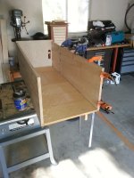
Status update: bottom and baffle are in. Before you scream at me and say well you screwed up because there is no hole in the bottom at the mouth I'll explain to you what I chose to do with that part. -> Instead of having an uneven base (just a piece connecting the front to the baffle and not having the rear side extend all the way down (limited to 48 inch material) I chose to make the bottom endcap out of a solid piece and route out the hole with a flush cut bit.
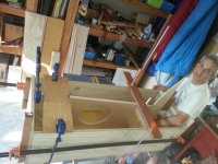
Look at all the jigs and clamps I'm using to make sure the baffle is square, at the correct angle, and 100% flush in every way! The spacing of the baffle is within a 1/16 of an inch in every direction of where it is modeled and has a constant expanding path of 8 -8 3/4 as it rounds the bend. The pictures will show some of the (many) biscuit joints I used for alignment and strength, there are roughly 2-4 per panel. This sucker is rock solid and I just used a router to flush cut the entire bottom end so the endcap sits flush with the sides (better than to 1/64th). My dad makes my workmanship go from airtight is good enough to cabinet grade only 🙂. Really helpful to have an extra set of hands and another mind to tackle issues like the endpiece.
First photo just shows the endcap going on, don't fret, the mouth hole will be jig sawed/routed after curing completes.
Middle picture, just a shot of the Makita that is a lifesaver for a number of reasons along with some of my dad's clamps.
You can see my dad in the last photo, he smiled immediately after but looks like i was quick on the trigger. AFAIK he enjoys helping me speaker build and it makes it much more enjoyable 🙂.
Attachments


Driver offset (within the rear or throat chamber) is actually one of the things i was going to ask David about ..
Hi MMJ,
The rear and throat chambers are modelled as cylinders symmetrical about the centre-line axis of the driver, as shown in the schematic diagram. The driver cannot be offset in the chambers.
Kind regards,
David
XRK,
Ill be damned!
That is definitely familiaresque ! I had never seen this particular box before but it has some similarities to the boxes we were looking at earlier in this discussion ... Tapped 6th order series tuned, with a large throat chamber followed by a constricted path which is followed by the tap and mouth..
The amount of driver offset (about 1/3rd of total path) combined with the extra resonator section looks like it has almost entirely suppressed the third harmonic and provided some extended bandwidth .... Neat Stuff! Thanks X , Good find!
Yes, it does extend the usable bandwidth, and this is especially useful for small horns.
I was looking for a way to publish this article here on diyaudio, just posting it did not seem right considering Kvalsvoll Design is a registered company.
I sent some information to one of the staff members here, but never got a reply, and I did not follow it up, it was really not that important for me.
I have developed several subwoofer designs now incorporating this technology, it works fine, within its limits, though.
The T138 is a medium-sized subwoofer with decent capacity if used in pairs or four, the smallest I have here now is using a 6.5 driver in a 14l net volume producing usable output down to 30Hz.
The larger ones produce usable output, and some more, all the way down.
The article on my web site should provide enough info to get started on some experiments, be prepared to use some time experimenting on the damping inside the channel, measurement is mandatory.
For those who are interested, these are the modified hornresp sizes measured directly from my current build based off builders tolerance: you know those times when you have to trim the bottom because of a void and the width somehow ends up a 1/32 over and you based the driver spacing based on memory. The actual product is actually darn close to what was expected and I went to great pains to make sure that the path expanded around the end (8->8.2->8.4) and thus the baffle was trimmed ~.75 to go with .5 trimmed off the height of the cab.
TLDR: this is the model that most accurately reflects what is being built to date and is accurate to as good as my ruler/eyes can handle.
P.S. I have this really beautiful CAD drawing of the thing with even more accurate definition/planes now (thanks dad). Great thing is I plan to upload a free to view EASM file so anyone can play around with viewing/measuring the model. More on that later.
Attachments
Hi MMJ,
The rear and throat chambers are modelled as cylinders symmetrical about the centre-line axis of the driver, as shown in the schematic diagram. The driver cannot be offset in the chambers.
Kind regards,
David
Ok, i see, thank you for getting back to me on this David, i was more-or-less just trying to find a way to sim the effect of moving the driver around within the smaller chamber of my recently posted 8th order transflex designs .... I think i have figured out a solution to this by turning my 8th order idea completely upside down by making the rear chamber into my main pipe (tuned to the fundamental 40hz ) and allowing S1-S5 to be the small chamber , that way i can shift the driver position tap around to alter the midbass response 🙂 It appears to work so far and even allows me to add filling to the small chamber, NEAT!😀 ..
Much appreciation,
MMJ in Arizona
Last edited:
Ok, i see, thank you for getting back to me on this David, i was more-or-less just trying to find a way to sim the effect of moving the driver around within the smaller chamber of my recently posted 8th order transflex designs .... I think i have figured out a solution to this by turning my 8th order idea completely upside down by making the rear chamber into my main pipe (tuned to the fundamental 40hz ) and allowing S1-S5 to be the small chamber , that way i can shift the driver position tap around to alter the midbass response 🙂 It appears to work so far ..
Much appreciation,
MMJ in Arizona
MMJ - I just sent you a PM
Hi Matthew Morgan J,
Post #697: "... think i have figured out a solution to this by turning my 8th order idea completely upside down by making the rear chamber into my main pipe..."
It would be much easier to follow your description, and maybe to help, if you would add Hornresp reference lables to you sketches (S1/S2...Vtc...Vrc...). Also, by Hornresp convention the sound has to pass from S1 past S2 and S3, and also by S4 on its way to S5, I don't think that is the case in Post #691.
Just interested, and trying to understand.
Regards,
Yes, it does extend the usable bandwidth, and this is especially useful for small horns.
I was looking for a way to publish this article here on diyaudio, just posting it did not seem right considering Kvalsvoll Design is a registered company.
I sent some information to one of the staff members here, but never got a reply, and I did not follow it up, it was really not that important for me.
I have developed several subwoofer designs now incorporating this technology, it works fine, within its limits, though.
The T138 is a medium-sized subwoofer with decent capacity if used in pairs or four, the smallest I have here now is using a 6.5 driver in a 14l net volume producing usable output down to 30Hz.
The larger ones produce usable output, and some more, all the way down.
The article on my web site should provide enough info to get started on some experiments, be prepared to use some time experimenting on the damping inside the channel, measurement is mandatory.
OKV ,
This is great to hear!
I would love to see some of your work, if you ever feel comfortable in doing so please share some pictures or weblinks when you can? Or if not feel free to send me something in private .. 🙂
- Home
- Loudspeakers
- Subwoofers
- New sub design? Constricted Transflex, simple build (series tuned 6th order)