While I was waiting for a response from Usher, I found something very interesting and it turns out Mr. Pass is right about the production for Threshold by Usher. Already in 1982, there was an exact copy of the Threshold power amplifier with a dedicated preamplifier on their market, see the rest for yourself in the attached photos and for more please see the link: https://tcwfjean.blogspot.com/2018/11/usher-p-202-reference-2.html
This is very interesting, in the brochure we see Usher R-2 and R-3 just like Stasis 2 and 3. Coincidence? I do not think so. In the link, pay attention to the interior of the preamplifier with the Usher brand on the front and inside? It's all very weird.


This is very interesting, in the brochure we see Usher R-2 and R-3 just like Stasis 2 and 3. Coincidence? I do not think so. In the link, pay attention to the interior of the preamplifier with the Usher brand on the front and inside? It's all very weird.
Last edited:
Greetings to my DIY brethren. I journeyed to the mountain top, my quest to obtain the sacred scrips illuminating the second coming of the Stasis front end. As I raised my staff in supplication, I was blinded by lightning and the voice of the mighty ZM rang out:
isn't it already in post #1 ?

isn't it already in post #1 ?

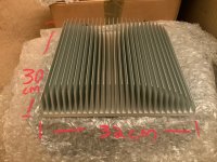
I’m thinking of going 11 way ie. 1 + 5 +5 per channel using these heatsinks, one OS board mounted above the other.
Am I correct in thinking that I only need one FE board per channel ie the second OS board is just a extension of the primary board ?
Am I correct in thinking that I only need one FE board per channel ie the second OS board is just a extension of the primary board ?
Attachments
Yes I get that thanks ZM, but if I “extend“ the OS board by adding a second OS with 5 additional output devices (to give 11 devices in total per channel), then am i right that I still only need 0ne FE board per channel?one FE + one OS pcb is basic format for one channel
yes, second OS just being parallel extension to first one
and - you don't need final drivers populated on that second one
and - you don't need final drivers populated on that second one
Actually, having the second set of Stasis transistors driving the Current outputs while not necessary with so few Current transistors would not hurt. For the SA/1 amps with 18 current and 2 Stasis transistors put board it works better.
Another member has some 2SA1294 / 2SC3263 that I can buy, but I’m about 6 pairs short. Does anybody have any spare that I can buy, ideally in the UK or EU?
2SA1294 / 2SC3263
Maybe from here:
https://www.profusionplc.com/parts/2sa1294
https://www.profusionplc.com/parts/2sc3263
Maybe from here:
https://www.profusionplc.com/parts/2sa1294
https://www.profusionplc.com/parts/2sc3263
I did not understand anything 🤔Greetings to my DIY brethren. I journeyed to the mountain top, my quest to obtain the sacred scrips illuminating the second coming of the Stasis front end. As I raised my staff in supplication, I was blinded by lightning and the voice of the mighty ZM rang out:
isn't it already in post #1 ?
I did not understand anything 🤔
Vivid explanation is in post #1224
Hi,
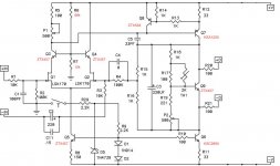
I want to adapt this front end to work with my S/500 amp as a fun project. I have been compiling a BOM based on what I have read here. From what I can gather, I should populate the front end up to the -D and +D and leave the rest empty. Attached is the BOM and Schematics that I have so far.
BOM for a S/500 with 2020 Passworks front end
S/500 has 76v rails
Resistors: (All resistors outside of Zen’s suggestions in post 860 are Vishay/Dale CMF 1/2w)
R1 = 1k
R2 = 100k
R3 = 10k
R4 = 100k
R5 = 100
R6 = 68k (Zen’s Board R8) See post 860
R7 = 12k (Zen’s Board R9) See post 860
R8 = 150
R9 = 2.2k
R10 = 100
R11 = 33
R12 = 33
R13 = 1k
R14 = 1k
R15 = 1k
R16 = 1k
R17 = 100
R18 = 1k
R19 = 221
R20 = 100
R21 = 100
R22-R28 for Cascode amps only
Capacitors:
C1 = 100pf Wima Film https://www.mouser.com/ProductDetail/505-FKP2D001001DJI00
C2 = 220uf https://www.mouser.com/ProductDetail/647-UFG1E221MPM1TD
-Note, lead spacing on C2 is 2.5mm. The cap in the link is 5mm. I wanted to use either a Elna Silmic or Nichicon Muse
C3 = 220uf https://www.mouser.com/ProductDetail/647-UFG1E221MPM1TD
-Same capacitor as C2 but lead spacing is appropriate
C4 = Empty at first. See note.
-Used to adjust the Square wave when testing using oscilloscope at 1kz
C5 = 33pf Wima Film https://www.mouser.com/ProductDetail/505-FKP2O10331D0HF0
C6-C10 = Empty. Used for a Cascode output amp
C11 = .15uf Wima Film https://www.mouser.com/ProductDetail/505-MKP2D031501HJI00
Thermostat:
T = Normally Closed, opens at 65 degrees Celsius
- https://www.mouser.com/ProductDetail/Sensata-Technologies/1NT01L-7936/?qs=F5EMLAvA7IB762eDTGcnig==
Thermester:
TH = NTC 2k
-https://www.mouser.com/ProductDetail/Amphenol-Advanced-Sensors/NK202C2R5?qs=P8zB4ONU6fwHz58laAezVA%3D%3D
Diodes:
D1 = 1N914
D2 = 1N914
D3 - D4 = empty ( For Cascode output)
D5 = 1N4739
Active Devices:
Q1 = LSK170
Q2 = LSK170
Q3 = ZTX457 NPN (Q3 and Q4 matched)
Q4 = ZTX457 NPN (Q3 and Q4 matched)
Q5 = ZTX457 NPN
Q6 = KSC2690 (can use 2SC3503)
Q7 = KSA1220 (can use 2SA1381)
Q8 = ZTX558 PNP
Q9 = ZTX457 NPN
Attachments
Thank you, that really helps.
I will add this to the list:
https://www.mouser.com/ProductDetail/Elna/RFS-25V100MF35?qs=HV/SjD3ivR9dMGAV9Am60Q==
I will add this to the list:
https://www.mouser.com/ProductDetail/Elna/RFS-25V100MF35?qs=HV/SjD3ivR9dMGAV9Am60Q==
I did go intentionally with physical dimensions of parts Pa did chose
same with values
but, as always, there is some leeway to improvise/make another decision
C2 value is strictly in correlation with 10K series resistor
Fc=1/(2*Pi*R*C)
10uF is givin' ya corner of 1.6Hz
who cares ....... some with toy Sonus Fabers etc. should go with 1uF, no penalties
same with values
but, as always, there is some leeway to improvise/make another decision
C2 value is strictly in correlation with 10K series resistor
Fc=1/(2*Pi*R*C)
10uF is givin' ya corner of 1.6Hz
who cares ....... some with toy Sonus Fabers etc. should go with 1uF, no penalties
Last edited:
Yeah, 1.6hz will do it. No Sonus Fabers here... Just any DIY stuff I can manage to build.
I tried using that formula and I got .00000159. I then tried it on a online calculator and got your 1.59hz. My arithmetic must be off. Thank goodness for Zenmod and Calculators.
I tried using that formula and I got .00000159. I then tried it on a online calculator and got your 1.59hz. My arithmetic must be off. Thank goodness for Zenmod and Calculators.

- Home
- Amplifiers
- Pass Labs
- New Stasis front end