Alright, wrong question then: it should have been more explicit as "the network that directly acts on the bias of the output devices". Btw this schematic doesn't even have 1 single bypass cap (explicitly on network B).
It's just a word play 🙂
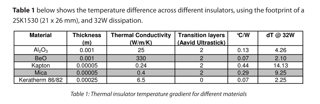
Back to the previous topic: I didn't know anything about the Keratherm; looking at EUVL's chart, it's like 4x better than mica, and 2x better than alumina, but costs nearly as much as the power transistors. Any other alternatives?
Back to the previous topic: I didn't know anything about the Keratherm; looking at EUVL's chart, it's like 4x better than mica, and 2x better than alumina, but costs nearly as much as the power transistors. Any other alternatives?
... costs nearly as much as the power transistors. Any other alternatives?
Zung,
By cutting them myself I save a ton, I paid $25 USD for a 210x148x0.25mm sheet that when cut I get from 58 to 72 TO-3P sized pads so that's cheaper, attached are the cut list options if anyone is interested.
Attachments
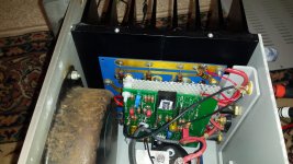
FE board in and tested
Finally finished one side of the s150. did some preliminary testing with no load (looked very clean in the scope.) Bias and dc offset was very sensitive even that I used a 25 turn pot. Bias were adjusted to about 160 mv cold. After one hour they were at 300 mv and the heatsink was at 45 degrees. Will do further tunning and finish the other channel.
Finally finished one side of the s150. did some preliminary testing with no load (looked very clean in the scope.) Bias and dc offset was very sensitive even that I used a 25 turn pot. Bias were adjusted to about 160 mv cold. After one hour they were at 300 mv and the heatsink was at 45 degrees. Will do further tunning and finish the other channel.
Attachments
FE board in and tested
thermistor on heatsink?
top lid closed ?
Yes, t is embed in a hold inside the heat sink (stock original from the Treshold amp). Thermistor is in the surface of the os board touching the bold that holds the board to the heatsink.
Top lid semiclosed just resting in the top of the amp as i have the meter cables hook the emiter in order to take the readings.
Any suggestion?
I believe Pa made it in same manner as ole Treshold amps, regarding biasing
read this, draw some conclusions, write back if needed
as I said, I'm not going to test it and/or build it (even if I recently decided to put FE in small Hitachi Mosfet amp) , so Mithrandir is a guy to bother
 ......... as always - blame Pa ...........
read this, draw some conclusions, write back if needed
as I said, I'm not going to test it and/or build it (even if I recently decided to put FE in small Hitachi Mosfet amp) , so Mithrandir is a guy to bother
......... as always - blame Pa ........... Attachments
FE boards in, preliminary audition
Got everything square out. Critical and final dc offset and bias still to be performed. Im to desperate wanted to listen to some tunes. But here it is bias adjusted to final temp of 42/43 degrees. Dc offset both channel to -5 mv. More critical adjustment can be done but need more patient.
Preliminary listing, harshness is gone (previously I have equalized the speakers to tolerate the harshness). Soundstage is more and I mean much larger (Horizontal). Deep also improved, more 3d. OOOO the mid are sweet!!!!! It brougth tears to my eyes, wanted to hear more and more of my music collection. But fine tuning needs to be done.
However, I cant compare to a good working s150 since my was not working properly. I dont know but the new FE it is worth the effort.
I will like to thanks all does that help me throughout this little project, (special to ZM) Thanks!!!!

.........
However, I cant compare to a good working s150 since my was not working properly. I dont know but the new FE it is worth the effort.
.....
if Mithrandir said - it is improvement of original design, be sure it is .......
.........
......
I will like to thanks all does that help me throughout this little project, (special to ZM) Thanks!!!!
naah
always blame Pa, and only Pa ........
🙂
btw. - you already know - no porn, no glory ........ how do we know that you aren't just telling stories

I count three bias networks: labeled A, B, and C.
_
It would also seem that Q6 and Q7 are the wrong sex.

It would also seem that Q6 and Q7 are the wrong sex.
Oh!
That's why the thing doesn't sound right! 🙂🙂🙂
The schematic is from the official site, so it has to be error free.
Slightly different topic: while shopping for output transistors, I bump into some "Used Old Stock" Toshiba 2SA1302/2SC3281 for a buck a piece that measure quite nicely.
Last edited:
Im attempting to do my first pcb layout here making a Zen stasis front end for my hafler p125 I have a few questions ill try and keep them to yes or no, ZM started out with this
so if i place pads for v+ v- and ground with through holes and studs, attach the BJTs to the back attach v+ v- and grouand from the transformer to the front essentially making each one of these points a star will that work?
In addition to a fuse on the mains, the p125 has fuses on the rails should I keep or omit these?
RG1 on zen mods schematic from the original Hafler circuit is R18/470 on the dh-120 schematic and RG2 is R21/68 on the dh-120 schematic, is this correct?
dont laugh, i dont have my head around this, my thinking is to move the connections next to Q5 or Q7 or both to one side or the other of RG1 and or RG2 or maybe something similar with the connection at C6? Am I even close?
and then theres the talk about the NTC and this....
so i can design the board and completely understand this later? or not so much?
Thanks !!
little creativity with wiring (rails first to mosfet cases with fat wires, then tiny wires to FE), it is as this (attached pic)
so if i place pads for v+ v- and ground with through holes and studs, attach the BJTs to the back attach v+ v- and grouand from the transformer to the front essentially making each one of these points a star will that work?
In addition to a fuse on the mains, the p125 has fuses on the rails should I keep or omit these?
RG1 on zen mods schematic from the original Hafler circuit is R18/470 on the dh-120 schematic and RG2 is R21/68 on the dh-120 schematic, is this correct?
moving NFB takeout point from R17/R18 node , to output
dont laugh, i dont have my head around this, my thinking is to move the connections next to Q5 or Q7 or both to one side or the other of RG1 and or RG2 or maybe something similar with the connection at C6? Am I even close?
and then theres the talk about the NTC and this....
in case you can't get Iq of your choice (without source resistors either observe at R in CRC PSU filter, or with DC current clamp ditto on rail wire to drain) , just increase R20 to some bigger standard value
ref. to schm in post #670, say that 1K2 for R20 should give 4V47 , while original (1K) value should give 3V88 between mosfet gates
so i can design the board and completely understand this later? or not so much?
Thanks !!
- Home
- Amplifiers
- Pass Labs
- New Stasis front end