ZM could you expand on your Hafler musings? I have a p125 that would very much like to achieve stasis.
I believe Papa's FE should have enough voltage range across mid bjt in biasing vertical, to cover all what lateral mosfets in Hafler OS needs
it'll be not Stasis OS, but worthy of this FE
it seems I can't find (quick and easy) P125 sch
do you have it?
it'll be not Stasis OS, but worthy of this FE
it seems I can't find (quick and easy) P125 sch
do you have it?
The dh120 might have the same schematic but they are not identical, the dh has a single board per channel while the p125 has 2 and speaker protection I believe. Hafler does not have a p125 specific manual as far as I know.
DH 120 does not seem to be from Papa Ernö’s mind, https://hafler.com/pdf/archive/DH-120_amp_man.pdf .
Greenhorn incoming…
The switch T. I saw the answer that it is a Thermostat, but could someone point me on Mouser what one of these looks like please?
Also, I was confused about the TH1 being either a NTC or PTC, which one is it supposed to be? I assume like the one in the F5T which needs to rest on the heatsink. Again, I would be very grateful if someone could point me at a Mouser part please.
Ta.
There is a valuable analysis and discussion of Inrush Current Limiter devices at (part numbers included):
Not thrilled with CL-60 inrush limiter in USA/160W Class A First Watt designs
will get you schm for bstrd soon
There is a valuable analysis and discussion of Inrush Current Limiter devices at (part numbers included):
Not thrilled with CL-60 inrush limiter in USA/160W Class A First Watt designs
take care that here is "small signal" NTC, not inrush current limiter

Thanks for pointing that out Zen Mod!
good try, but no go ........ it's well known who's Undisputed King of Dodossness around

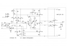
here it is
little creativity with wiring (rails first to mosfet cases with fat wires, then tiny wires to FE), it is as this (attached pic)
few things worth trying :
- moving NFB takeout point from R17/R18 node , to output ...... maybe that would squeeze some more damping factor from puny verticals
-NTC could stay mounted on pcb, counting on friendly TempCo of puny verticals
usual disclaimer - blame Pa for everything, which includes each and every stupidity I make in public
🙂
Attachments
Hmmm...
I happen to have a few sets of matched Hafler lateral Mosfets, from the days when I was collecting old Hafler DH-220 amps just for the fun of it. Even have some matched triples or quads if I'm not picky about them being sourced from the same amp. Just matched by the Hafler number stamp on each part. I also still have the old power transformers, some in matched pairs for dual-mono.
I'm willing to bet that the Stasis front-end will sound pretty good, especially when upgraded with modern components.
yup, easy to try
btw, I just ordered few FE pcbs, to finally make that Hitachi little jewel functional again
it seems big ugly and amateurish made original pcb is going to be tossed

btw, I just ordered few FE pcbs, to finally make that Hitachi little jewel functional again
it seems big ugly and amateurish made original pcb is going to be tossed
Last edited:
I would rather check for NTC of 2K, than 4R7
just in case ........
 Thanks again ZM!
in case you can't get Iq of your choice (without source resistors either observe at R in CRC PSU filter, or with DC current clamp ditto on rail wire to drain) , just increase R20 to some bigger standard value
ref. to schm in post #670, say that 1K2 for R20 should give 4V47 , while original (1K) value should give 3V88 between mosfet gates
ref. to schm in post #670, say that 1K2 for R20 should give 4V47 , while original (1K) value should give 3V88 between mosfet gates
...
loading of FE with OS shouldn't change much, or anything
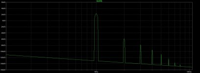
A remarquable FE it is: THD is <0.0006% with a resistive load from infinity down to 2K, with a beautiful harmonic spectrum. Adding 1nF in parallel with the load doesn't change the THD value, but the odd harmonics are a bit higher. At 1K load the protection kicks in.
Of course this is from LTspice; but even if it were an order of magnitude worse in real life, I'd still be happy.
Attachments
- Home
- Amplifiers
- Pass Labs
- New Stasis front end