hello everyone!
I don't get their intention behind the CD4053. Why didn't they use the mute input of the PCM1798? Would safe a component in the signal path?!
regards,
oliver
Yep. That's another thing on my list. I really don't like that 4053 in the signal path. It seems the DACs mute input would have been a better choice.
hi Kevin,
Are your mods referencing to this schematic?
http://img153.imageshack.us/img153/9063/dsc6604.jpg
thanks,
Piersma
Yes, that's right. It doesn't match what's on my board, for the final stage, at least.
Kevin
Maybe because the DAC mute it is too slow for what is intended (mute for loss of data stream)? From datasheet:
Soft Mute
The PCM1798 supports mute operation. When MUTE (pin 10) is set to HIGH, both analog outputs are transitioned
to the bipolar zero level in –0.5-dB steps with a transition speed of 1/fS per step. This system provides pop-free muting
of the DAC output.
Last edited:
Maybe because the DAC mute it is too slow for what is intended (mute for loss of data stream)? From datasheet:
I can't see a problem with that. All that appears to be saying is that if the output is non-zero when the mute signal is asserted, it ramps back to zero rather than changing instantaneously (which would cause a "pop").
I will have to try it on mine and see if it works.
Kevin
Hello. It is my first text.
I bought the DAC in September 2010. Blue plate comes with three ad827.
By removing the mute DC4056 produced a decrease in harmonic distortion pair. Shorting contacts of this is god idea.
No mute and no signal to SPDIF input, noise occurs at the output. Need to move the mute signal coming out of Q1 to terminal 10 of DAC. I will try it in the future.
You don’t need to put resistors on the output to improve the sound. Better is to put + -15 vol analog power supply.
When using originally + -12 Vol the Op Amp. U11 and U12 saturate when the DAC signal is above -10 dB. In that case replace 820 Oh. resistor by a 300 Oh. or put 470 Oh. in parallel with R29 and R30 R28 R27. A important reduction of even and odd harmonic distortion. Best S/N + -15 Vol.
There is a slight improvement if replace U11 and U12 (two AD827) for two OPA2134. And also a slight improvement by replacing U9 (AD827) for OPA2406.
🙂
Last edited:
Greets,
I just received shipping confirmation for my Gigawork. I plan to combine it with the Shigaclone.
That will be me back there hanging onto your shirt-tails...😀
I just received shipping confirmation for my Gigawork. I plan to combine it with the Shigaclone.
That will be me back there hanging onto your shirt-tails...😀
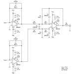
Definitely the 4056 is not the best ideea. Alternative would be the intended mute pin OR a mute circuit with two transistors as it is done everywhere else:
An externally hosted image should be here but it was not working when we last tested it.
Last edited:
Original R27, R28, R29 y R30: 820 Oh. (+-12Vol.)
Modified 300 Oh. (470 // 820 Oh. OK for +-12 Vol.).
Best option 820 Oh. ( OK for +- 15 Vol)
Modified 300 Oh. (470 // 820 Oh. OK for +-12 Vol.).
Best option 820 Oh. ( OK for +- 15 Vol)
An externally hosted image should be here but it was not working when we last tested it.
Awesome, are your pics or just linked to "lampucera2"?
I would like to know what other OpAmps did you try. Looks like you could test easy some LM4562, NJM2068 or older LM833, NE5532...
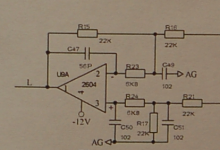
my DAC-board has the same part-values, which are totally different from those mentioned in their own schematic.Just looked in more detail at mine and it's worse than I thought. All resistors in the output filter apart from R15 and R18 were 1k ohms on mine. R15 and R18 are 1k5 (meaning there's a large DC offset at the output).
thanks for the confirmation that the 4053 is quite useless.
i think i discovered another error at that point: if you take a look in the datasheet of CS8416 the port description of NV/RERR says something likeNo mute and no signal to SPDIF input, noise occurs at the output. Need to move the mute signal coming out of Q1 to terminal 10 of DAC. I will try it in the future.
this means that NV/RERR is an input, but they used it as output for the mute signal. if you look at the schematic you will discover that the 47k resistor that should be connected to NV/RERR is connected to the AUDIO-output. can anyone confirm this error? i'm a bit unsure, cause i tend to make some errors on my own 😉.Non-Validity Receiver Error/Receiver Error (Output) - Receiver error indicator. NVERR is selected by a 47 kΩ resistor to DGND. RERR is selected by a 47 kΩ resistor to VL.
i think the correct connection would by pin 415 (wtf?) from cs8416 to pin 10 from the PCM1798 and the 47k resistor to pin 14 of CS8416.
another thing to mention: the LED D2 is connected to +3,3V not to GND as shown in the schematic.
where do you get this voltage? directly from the bridge? is this ok, without regulation?You don’t need to put resistors on the output to improve the sound. Better is to put + -15 vol analog power supply.
thanks,
oliver
Last edited:
i have replaced the original output stage by this one. up to now it sounds good to me, but i think i'll have to do some further listening.
another thing to mention: my original transformer makes some noise (like internal vibrating), i have contacted gigaworks and my replacement should be on the way. nice support. anyone else with this noise problem?
regards,
oliver
another thing to mention: my original transformer makes some noise (like internal vibrating), i have contacted gigaworks and my replacement should be on the way. nice support. anyone else with this noise problem?
regards,
oliver
i think i discovered another error at that point: if you take a look in the datasheet of CS8416 the port description of NV/RERR says something like
this means that NV/RERR is an input, but they used it as output for the mute signal. if you look at the schematic you will discover that the 47k resistor that should be connected to NV/RERR is connected to the AUDIO-output. can anyone confirm this error? i'm a bit unsure, cause i tend to make some errors on my own.
i think the correct connection would by pin 415 (wtf?) from cs8416 to pin 10 from the PCM1798 and the 47k resistor to pin 14 of CS8416.
another thing to mention: the LED D2 is connected to +3,3V not to GND as shown in the schematic.
Regarding the mute'm reviewing as I believe that if the circuit is pin 14. And I see if have to use normal or inverted.
where do you get this voltage? directly from the bridge? is this ok, without regulation?
15 vol is recommended in the Burr Brown aplication note. Would have to change the transformer and regulators to 7815 and 7915 instead of 7812 and 7912.
Firts I'm seeing if we can up the voltage because I dont know if the electrolyte capacitors have 15 V. I think it's best to put new capacitors.
With the OPA2604 OPA 2124 could up to 18 V. even better, ¡¡no AD827!! ¿Value R I/V circuit?
You can get a high-end DAC with 2 x GigaWorks DAC 3xOPA2604 power suply + -24 Vol.
Mono. Balanced output. It's easy to put Mono and balanced.
Awesome, are your pics or just linked to "lampucera2"?
I would like to know what other OpAmps did you try. Looks like you could test easy some LM4562, NJM2068 or older LM833, NE5532...
These are pictures of me.
I have only these Op Amp. Maybe someday get others for measure and listen it.
I measured Burson, was best. But it´s too much expensive for this DAC.
I'm sorry, i don't understand what you mean.Regarding the mute'm reviewing as I believe that if the circuit is pin 14. And I see if have to use normal or inverted.
i've seen that. after all, why do we need such voltage levels? i thought the typical high level input voltage at power amplifiers is around 6,8 V or is this RMS and not peak to peak? lots of things to learn for me at audio...15 vol is recommended in the Burr Brown aplication note.
12V of the transformer should be around 17V after rectification, that could be sufficient for those regulators. they typically call for a input voltage 2V above the desired voltage (would be 17V). but i also haven't yet checked the capacitors.Would have to change the transformer and regulators to 7815 and 7915 instead of 7812 and 7912.
i'm currently using LME49720 (in the magic metal can...) but i didn't really recognize any change in acoustics by replacing the opamps. changing of the summation circuit was ways more audible.
regards,
oliver
Hi, 7812 and 7912 are more than enough with modern opamps that can swing to nearly supply voltages at the output. You won't win much by changing them to 7815/7915 or it should be peeled off PCB tracks.
I have a device that has an output stage running on + and - 5V which clearly does not provide enough headroom. In that case a higher supply voltage is necessary.
I have a device that has an output stage running on + and - 5V which clearly does not provide enough headroom. In that case a higher supply voltage is necessary.
Normal-inverted= mute 0 or 3,3 Vol.I'm sorry, i don't understand what you mean.
How to calculate optimal V and R do not know. I have insufficient data or graphs. Distortion, noise and maximum (0 dB DAC, 4 mA) to the operational output depends: R in V / R, output, power suply, temperature, etc. .. But it is easy measuring.
Manufacturer recommends: 15 820 Oh. Vol. (Vs = 3.28 = 0.004 X820)
Tests good for the 3 measured Op. Amp. 12 Vol 300 Oh. (Vs = 1.2 x300 = 0.004).
Example: (LME49720 for me optimal 15 vol. 500 Oh. (Vs = 2 = 0,004 x500).
Op Amp Data all have many graphs specifications:
Graphic LME49710 similar LME49720 to be understood the example.
Choose the maximum output voltage before clipping begin. Where the Op Amp is linear. Remember we want to High End Sound.
An externally hosted image should be here but it was not working when we last tested it.
An externally hosted image should be here but it was not working when we last tested it.
Yes, and it sound so bad and feedback is required.Hi, 7812 and 7912 are more than enough with modern opamps that can swing to nearly supply voltages at the output. You won't win much by changing them to 7815/7915 or it should be peeled off PCB tracks.
But it also can sound good and lees feedback if used properly. 😀
Normal-inverted= mute 0 or 3,3 Vol.
pin14 NV/RERR is high active, meaning that its voltage is 3,3V if there is a error condition. by that it should be possible to use this pin as mute signal for the pcm1798. there is no error in the schematic, i misunderstood the intention of the pin. it is sensed on startup (to select NVERR or RERR) and afterwards used as output for the corresponding error status.
however, the part Q1 seems to be omitted at my PCB. i didn't find it and measuring gives a direct connection between R9 and R10.
thanks for your explanation about the opamp voltage. made things clearer to me.
regards,
oliver
- Status
- Not open for further replies.
- Home
- Source & Line
- Digital Line Level
- New Small DIY Gigawork Dac?