I got the boards they are beautiful. Thank you! Placing my mouser order. Do you have part numbers for AC and primary connection terminals(blades or whatever you call male part of those crimp terminals)?
anybody willing to share their parts list or mouser cart? I'm crunched for time these days, well and I hate hunting for parts.
I got the boards they are beautiful. Thank you! Placing my mouser order. Do you have part numbers for AC and primary connection terminals(blades or whatever you call male part of those crimp terminals)?
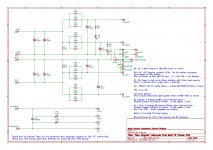
See the schematic on post #1. There’s a molex part number example. I’ve used other brands too.
Boards arrived yesterday. They look fantastic! Thanks Randy - what a great service you are giving us. I am humbled by the generosity displayed by members of this community. How can this beginner return such gallantry?
I'm glad the postal service is getting these out in a timely fashion!
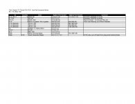
I've never done an mouser cart. I'm more of a Digikey guy...
Here are some suggested parts at Digikey.
Notes:
They're out of 0R33 Panasonics. I use the Yageo's. You could also try 0R47 and be just fine.
I put a lot of different filter caps in that will work. from 22k up to 47k. If you like a certain brand, just look for 10mm lead spacing and up to 35mm diameter. I used to overthink cap selection. But as it's been said - "After all, this is entertainment, not dialysis."
For quick disconnects that mate with the blades, I always end up at Home Depot and get the packs of blue connectors. Sometimes for fat transformer wires you need the yellow connectors. Best to get both. And get extras, you'll botch a crimp or 3 if you're not used to it. And you'll still botch some if you're used to it. Home Depot also sells the packs with female connectors only. If I recall Lowes sells the combo packs, which get half used. Maybe same at Menards. Home depot is my go-to for these.
Attachments
Mine is actually made up of different parts of V1-3. I'm running 2 trannies per half, no diodes but using cascaded frontend. 33-34 rails. 1.3 amp bias on each trannie. 2Kva transformer. Sounds real good just mocked up on bench.
Yes so I would look at 2 boards more than likely.
Yes so I would look at 2 boards more than likely.

Looking great! Looking forward to feedback on them.
You're going nonstop. VFET then F6 back to back!
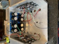
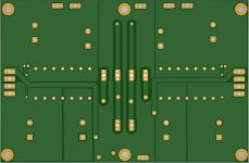
I never expected to see those quick disconnect terminals in the center of the PCB. How did they fit? I don't think I considered spacing for those, so maybe it's a bit if luck they're fitting.
You're going nonstop. VFET then F6 back to back!
I never expected to see those quick disconnect terminals in the center of the PCB. How did they fit? I don't think I considered spacing for those, so maybe it's a bit if luck they're fitting.
Actually remaking F6 with this psu. That F6 is one from the very first run with SS R100 and adjustable THD.
For the connectors I had to shop specifically for the spacing, the pins fit tightly, do fit. I can look up the part number if people are interested. I had to bend thermistor legs a bit to push them away a bit. So yes,if you are gonna do another revision some day consider some standard spacing then people can have more options for the terminals that fit without any creative part placing.
For the connectors I had to shop specifically for the spacing, the pins fit tightly, do fit. I can look up the part number if people are interested. I had to bend thermistor legs a bit to push them away a bit. So yes,if you are gonna do another revision some day consider some standard spacing then people can have more options for the terminals that fit without any creative part placing.

All good. 23V and 22.8V nice and quiet.
Super work!!! Thanks for the pic and note.
Can you send the part numbers on those angled quick disconnects? I can adjust spacing for those in for the next run.
Are you putting LED's on board or front panel? I see the resistors, but no LED's.
I made this for my friend and he wants purple LED's -- go figure, so I do not have those on for now.
These are the terminals I used:
1720017 Phoenix Contact | Mouser
Using those would require moving the thermistors like 3mm towards AC line input side. Also maybe 120A 120B 0A 0B print a bit further so it is readable.
Probably it will be better to use something a bit smaller:
https://www.mouser.com/ProductDetail/Phoenix-Contact/1720033?qs=Xflg4jNzfa4AqbLvIh%2Bf3Q==
or you can take a look at the entire list of angled disconnects:
https://www.mouser.com/Phoenix-Cont...0wxmoZ1z0wxohZ1z0wxg7Z1z0wxhyZ1z0wxlbZ1z0zljm
Hope it helps.
I made this for my friend and he wants purple LED's -- go figure, so I do not have those on for now.
These are the terminals I used:
1720017 Phoenix Contact | Mouser
Using those would require moving the thermistors like 3mm towards AC line input side. Also maybe 120A 120B 0A 0B print a bit further so it is readable.
Probably it will be better to use something a bit smaller:
https://www.mouser.com/ProductDetail/Phoenix-Contact/1720033?qs=Xflg4jNzfa4AqbLvIh%2Bf3Q==
or you can take a look at the entire list of angled disconnects:
https://www.mouser.com/Phoenix-Cont...0wxmoZ1z0wxohZ1z0wxg7Z1z0wxhyZ1z0wxlbZ1z0zljm
Hope it helps.
Very helpful. Thanks for the info.
Regards,
Dan 🙂

Any feedback from beta testers?
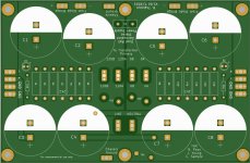
I'm going to do a little tweaking to better accommodate the Phoenix connectors that PKI used. Looking for any other feedback before I make run of these.
I'm going to do a little tweaking to better accommodate the Phoenix connectors that PKI used. Looking for any other feedback before I make run of these.
Updates made for the 35 degree big phoenix connectors PKI used.
Looking forward to other input from Beta Testers.
I'm attaching pix of a preview of the updated board design.
@BDP - stay tuned. I'll do a run later this month.
Looking forward to other input from Beta Testers.
I'm attaching pix of a preview of the updated board design.
If you do another run I would be interested in a couple boards.
@BDP - stay tuned. I'll do a run later this month.
Attachments
Any feedback from beta testers?
I have been using mine as a test bench supply for a while - had planned to get some measurements but that hasn't happened yet. It is a very robust power supply board - I like the ground isolation on the board and the connection options have worked for me.
rock steady voltages too - no changes needed on my end.
sorry it has taken me time to feedback - it is the old adage, if it is working and no niggles, there is no need to complain about improvements 🙂 . Thanks for allowing me to test this out.
..dB
- Home
- Amplifiers
- Pass Labs
- “New Original” Alternate First Watt F5 Tribute Power Supply PCB