Nor here - great thread, and very interesting reading (also - clear technical writing and well-illustrated which makes following your development process a joy @hpasternack); I'm looking forward to more tales from the bench.
Thanks. FWIW, I started working on a box for HPA2 this week. It's a painstaking process, and I'm taking my time.
Even though I said I was done with HPA1, it's nagging at me so I'm working on improving it. I'm thinking of switching from an EF-VAS to a cascode VAS to try to improve the clipping. I will report back if I have news.
Even though I said I was done with HPA1, it's nagging at me so I'm working on improving it. I'm thinking of switching from an EF-VAS to a cascode VAS to try to improve the clipping. I will report back if I have news.
Attachments
> I need to get some shorter screws.
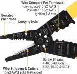
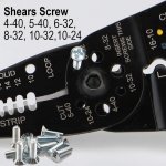
Good wire-tools have a screw-shortener.
https://www.amazon.com/Klein-Tools-1019-Connectors-Terminals/dp/B07GFYBW4V
https://www.amazon.com/Klein-Tools-1019-Connectors-Terminals/dp/B07GFYBW4V/
Some cover 4-40, 5-40, 6-32, 8-32, 10-32 and 10-24.
DOWELL Wire Stripping Tool Multi734
Note that you screw into the threaded side, so after you shear the un-screwing re-cuts the mooshed thread.
You can also screw a nut or two below the cut and hacksaw it. Unscrew nut to un-ruin the thread. File touch-up is good.
This for old-Imperial sizes. I dunno what to do about Metrics.
Attachments
Last edited:
Thanks. You mean like this? 🙂
I made a mistake and bought a hundred 3/8" screws when I wanted 1/4". I've been cutting them down. I'm too lazy to smooth the cut ends so I torque 'em in; saves me the bother of lock washers.
It bothers me to have cut screws in the amp, but I don't feel like driving fifty miles round trip to Bolt Depot, and too impatient to mail order, LOL.
Attachments

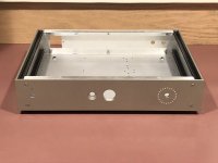
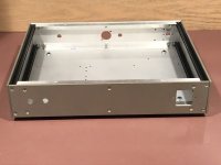
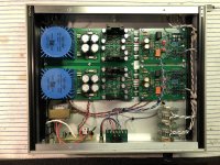
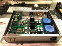
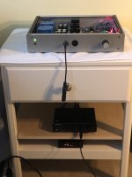
Well, in case anyone is interested, I got the HPA2 playing in its new box today. I need to get parts to build one of my SMD relay timer boards. In the meanwhile, I'm using the timer from the breadboard which is THT on a DIY PCB. I also need to find a prettier knob.
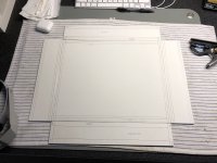
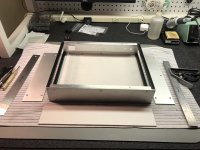
Building boxes is very challenging and time-consuming. I'm generally satisfied with how this came out, but need to continue to refine my technique to achieve tighter tolerances.
I think that's about it for the fun and games, folks. Lemme know if you want to try to build an HPA2. It's a challenging project, but IMHO the performance justifies the effort, if you're into this kind of thing.
Attachments
I actually considered doing an SMD layout for your HPA2 to avoid some of the EOL components in favour of modern SMD parts that I have lying around (and such nice things as dual matched BJTs for the current mirrors ). Sadly I do not have the time to start another project right now. However, I would still be interested in your gerbers - who knows, maybe I'll find enough reasons to order some Linear Systems dual JFETs in TO-71 from the US.
I've decided to make my HPA2 design files generally available. If it ends up on eBay, all the more power to our enterprising friends around the world.
Here is a Dropbox link: Dropbox - HPA2.zip - Simplify your life
If you want to play with the Kicad project, you will probably have to rescue some symbols. The process for doing that is left as an exercise for the reader.
I'll be happy to answer any questions related to this project, but otherwise, what you see is what you get. Real life demands attention, unfortunately.
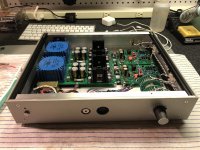
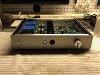
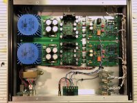
Thanks. For completeness: I put on a prettier knob and installed the relay timer from the DCG3. Next week, I guess I'll go look for a piece of perforated aluminum to put on top. TBH, looking forward to taking a break from audio projects. We'll see how long that lasts, hah.
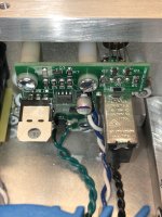
Edit: Minor construction hint: That little board underneath the XLR connector is DIY. I painted it with Testor's transparent green enamel, intended for model cars. Nasty stuff takes a long time to dry, but looks like authentic solder mask. It's not heat or solvent resistant, though, so be warned, it's only for aesthetics.
Edit: Another comment, this time on grounding, since it can be so problematic if not done properly. There are separate output and input stage grounds on the signal boards, separated by a 10 Ohm resistor, one per channel. The output grounds connect directly to the power supply and support the two output stage electrolytic bypass capacitors. The two XLR jack common terminals are soldered to the output board ground plane, establishing the signal common for both channels. The output and PC board input ground wires all connect together to the turret terminals adjacent to the XLR connector; the input jack ground shells are floating. The body of the 3.5mm output jack has a star washer behind the nut, making a connection to the chassis. This is the only signal chassis ground. The power inlet safety ground is also connected to the chassis adjacent to the socket. The result is no audible hum.
Attachments
Last edited:
Listening to both amps this weekend, I decided the HPA1 still sounds a little hard or splashy on strong percussion (Rolling Stones) compared to the HPA2. I have to apologize, but I'm just not confident of my ability to make out these differences, which other people might hear clearly (or not at all). In any case, I decided to remove the extra components and convert the HPA1 to traditional Miller compensation. SPICE says the phase margin is now 87 degrees, a little overcompensated. It does seems like it took a bit of the edge off, to good effect.
I've searched for subjective reports on the Blameless amp. There's not a lot out there, but there's a theme that says the Blameless is a little dry and forward in the midrange. Dunno what to say about that.
In any case, the amplifier still works after the change and I listened to it for a while and enjoyed it. I also tried comparing to the headphone jack on my late-model MacBook Pro. I don't want to exaggerate, but the DIY amps do sound better to me.
I'm still running the HPA1 without clamp diodes. I do believe removing them made a difference with TPC. As I wrote earlier, I speculate the difference will be less with plain Miller compensation. I did some SPICE simulations of this configuration, and it shows a significant rise in 2HD with the diodes in place. Still very low overall, though. Whether this is sonically relevant is anyone's guess. The next time I order parts, I will buy some more BAV21s and put them in to see if I can still hear a change.
I'm really on the fence about this objectivist/subjectivist thing. And I wouldn't want anyone to try to build these circuits, only to find they sound bad. I'm chilling and listening to some Phil Woods on HPA2 right now, not too loud, and thinking this is, well, pretty good sound.
Edit: Ok, I just switched to HPA1. Still having a good time with Phil Woods...
Attachments

Last edited:
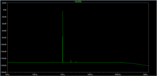
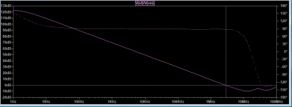
Something very interesting occurred to me a few weeks ago. I looked at it briefly then, and just spent some more time playing with it now in SPICE. If you look at my HPA2 compensation network, the intent was clear. I wanted to take the differential signals at the output of the VAS and run them through a differential, floating compensation network. Indeed, this seems to work very well and the resulting Bode plot is picture-perfect as I showed in an earlier post.
The problem, I realized much later, is that the voltages are not differential at this point. The VAS feeds a current mirror, and the load impedance in the left leg is very low. SPICE shows, as expected, that there is almost no signal voltage on the input side of my compensation network in that leg.
I thought to myself, "That was really dumb!" and removed the seemingly unnecessary compensation components. The result was the simulation went into oscillation. Looking at the frequency-domain plot, things were messed up. And I couldn't find a single-ended compensation scheme that worked nearly as well as the one in the original design.
Interestingly, I have seen a circuit like this in a paper I read recently, and it had only the single-ended compensation network. That's what prompted me to revisit this question.
So there's no emergency, but we're left with a mystery. I have a few ideas, but I need to think about it some more. Whatever is going on, it doesn't work quite the way I expected. It does, however, yield the desired result. Even though the impedances and voltages at the VAS output aren't balanced, the currents are, roughly. It could be that this is part of the answer.
In any event, I've now revealed to you that I have literally no idea what I'm doing, haha. But I've got dumb luck, and maybe that's all that matters in this case.
Attachments
I bought a Topping A30 Pro. If you believe Audio Science Review (ASR, LOL), this unit represents the apotheosis of headphone amplifier design. It has passthrough in/outs so I can quickly switch between the A30 and the HPA2.
Bottom line: the amps sound exactly the same, within the limits of my ability to hear a difference.
If you build the HPA2, I claim, you will be rewarded with state of the art sound.
Bottom line: the amps sound exactly the same, within the limits of my ability to hear a difference.
If you build the HPA2, I claim, you will be rewarded with state of the art sound.
Attachments
I’ve very much enjoyed following your thread. Your designs look great and I found the subjective listening tests interesting and quite similar to my own experiences. I certainly don’t have golden ears and find that I can listen to the same system on different days and have rather different experiences. Human perception is such a complex thing!
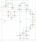
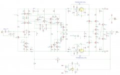
Thanks for sharing your designs. I’m hoping to make a variant of your HPA2, but with a few modifications to suit the parts that I have or can get easily (current draft schematic below). These include: more drastic high frequency filtering on the input, SMT transistors in place of TO92 in most places, LSK389 fets (as I have some already), KSA1220/KSC2690 in the VAS where the dissipation is highest (again, I have a some already), the ability to bypass the LDO regulators (I have some regulated +/-15V supplies that may be good enough and are worth a try on their own). I also moved to KSA1381/KSC3503 instead of TTx004B in the output, as I have some that are close(ish) in beta (~20% different) and simulations suggest that this mismatch should not be a major problem here, but we’ll see. The simulations look really good overall. If reality comes anywhere close this should be a great amp.
I wonder if I could ask a few questions that would really help?
* Do you think that any of my changes are poor choices that would significantly degrade your design? I'm a novice, please excuse the problems if they are there!
* I read in the semitech CRD datasheet that resistors can be used in parallel with the CRD to compensate for current fluctuations due to temp. Do you think that this would have any value in your design? I guess it’s not a big deal for D5, but perhaps D1?
* Was there a particular reason why you used BAV21 diodes throughout? There are so many choices when it comes to diodes. What characteristics do you feel are most important in these positions?
Thanks
John
Attachments
Everything you propose here seems very reasonable. I've started a couple times working on an SMD version of the HPA2, but TBH, I'm a little tired of designing PC boards and haven't made much progress. I'm very happy to see other people working on this circuit, and don't mind at all if folks modify it. My version is just one data point. The more the merrier. I'm very interested to learn how these projects turn out.
WRT your changes, it's midnight so I'm not going to go looking at data sheets right now, LOL. Q9, Q10, and Q13 see significant Vce and in a power amplifier the dissipation might be an issue. With higher voltage supplies, you would normally expect medium-power devices (TO-126 or TO-220) here. But because the rail voltages are low in a headphone amplifier, low-power transistors are probably ok. You're going to have more Cob with the bigger devices, and in principle that's a downgrade. It'll probably work fine either way, but it's something to think about.
About the CRDs, in an ideal world they would be perfect current sources. Typically, resistors are used here. So a basic CRD is an improvement, even if not an ideal infinite impedance. With regulated supplies, it's questionable whether the CRDs are needed at all. I wouldn't sweat it.
I put D1 in mainly to raise the impedance on the emitter of Q1, which reflects to its base, and which might have a very small impact on the common-mode rejection ratio of the input stage. I didn't bother calculating it, though. It's a second-order thing. I don't remember if SPICE showed a distortion advantage. If this were a commercial design, we'd probably take the CRDs out to save a few pennies in the BOM cost.
The main criterion for selecting diodes is junction capacitance. The capacitance varies with reverse bias voltage, so is a potential source of distortion when the diodes are switched off. I followed the recommendation at the bottom of this article by diyaudio member Bonsai: http://hifisonix.com/wordpress/wp-content/uploads/2019/02/Anti-Saturation-Diodes.pdf
1N4148s would work too, but are supposedly higher capacitance. I'm a little skeptical and half-seriously suspect all these switching diodes are exactly the same devices internally.
I seem to have learned a lot about circuits over the years, but don't have much insight into how things actually sound. Or maybe I'm just more honest than most. People in general are going to tell you the circuits they design sound great, and I guess I'm no exception. Whether those reports are reliable is another question, hahahaha. Seriously, I have no idea. I think Nelson Pass said, "It's all just entertainment."
A few other comments about transistor matching.
The BCM 847/857DS are not super-match pairs, and the hfe is lower than BC550/560. This will have some impact on performance of the current mirrors. I matched my devices very closely, and I glued them together, but of course thermal tracking will be better still when the transistors are in the same package. Ideally, you would buy a bunch of the BCM parts and hopefully find some that are exceptionally well-matched.
The 2N5564 is the highest-spec version of this device series. They were basically perfectly matched on my device tester. I hear the matching of the LSK389 isn't that close. YMMV.
I don't know if it's really that advantageous to use a matched pair for the VAS buffers, your Q6A/B. It can't really hurt, though. I'd be more inclined to use a matched pair for Q7 and Q8.
Similarly, though I matched the input cascodes (your Q3A/B) and glued them together, it's probably not super-critical to do so.
I measured hfe for my BC560Cs around 600. This is much higher than the spec for the BCMs, which have a typical value of hfe=250.
I apologize for being lazy and not having done a thorough analysis of the sensitivity of the circuit to mismatch of various device pairs... That would require thinking and hard work. 🙂
Thanks so much for all the helpful comments, that’s fantastic!
I certainly appreciate that the BCM8x7 are downgrades from the devices that you used. They are B-grade for hfe, rather than C-grade, as you noted. I did some quick tests in the simulations to see how sensitive the THD was to this drop in gain (@ 1kHz, 18Vpp, which is way more than I will need with my 80R phones) and there wasn’t any significant difference – exceptionally low in both cases. Hopefully real life will be as forgiving. The other downgrade is that these are not specifically low-noise parts, unlike the BC550/560. I’m not sure if this will make a big difference in this design or not. The upside is the termal tracking though.
All other discrete transistors in this version will be matched by hand. I wanted to use the BCM8x7 where possible to minimise the amount of matching, which I have to admit I find a bit boring – especially with fiddly SOT23 packages!
Absolutely – that’s the plan! The BCM8x7 pairs are specified with max. 10% hfe mismatch, which is not great. I was hoping that this was conservative and that I will be able to find some that are better than this amongst a reasonable sample, but I’ve not used them before, so we’ll see. Vbe matching is specified to 2mV max. mismatch at their test point. Realistically I don’t think I could get much better than this matching discrete devices with the cheap transistor tester I have, I don’t have that much confidence in its accuracy, so hopefully that’s not a major issue. I did look at a few other matched pair transistors, but didn’t spot anything else that looked ideal and some of the tightly matched pairs are super expensive! If anybody has any suggestions for duals to look at here they would be gratefully received.The BCM 847/857DS are not super-match pairs … Ideally, you would buy a bunch of the BCM parts and hopefully find some that are exceptionally well-matched.
I certainly appreciate that the BCM8x7 are downgrades from the devices that you used. They are B-grade for hfe, rather than C-grade, as you noted. I did some quick tests in the simulations to see how sensitive the THD was to this drop in gain (@ 1kHz, 18Vpp, which is way more than I will need with my 80R phones) and there wasn’t any significant difference – exceptionally low in both cases. Hopefully real life will be as forgiving. The other downgrade is that these are not specifically low-noise parts, unlike the BC550/560. I’m not sure if this will make a big difference in this design or not. The upside is the termal tracking though.
All other discrete transistors in this version will be matched by hand. I wanted to use the BCM8x7 where possible to minimise the amount of matching, which I have to admit I find a bit boring – especially with fiddly SOT23 packages!
- Home
- Amplifiers
- Headphone Systems
- New Headphone Amplifier Design