Connecting the collectors this way maintains a nearly constant, low voltage from collector to emitter of of the driver transistors. They are effectively cascoded. This has several advantages:
- Lowers driver transistor power dissipation
- Eliminates nonlinearity caused by Early effect
- Eliminates nonlinearity caused by nonlinear junction capacitance
- Lowers driver transistor effective input and output capacitance
Since the output transistors now carry the driver bias current, I think this helps the output stage stay in Class A.
I'm not aware of any disadvantages, but that doesn't mean there aren't any. Let's see what people say in your thread.
Edit: This has been asked before. See here: Questions regarding diamond buffers.
The driver transistors run at nearly zero Vcb. You want devices with a low saturation voltage here.
Edit: TBH, I didn't think of this latter point when I selected the TTA/TTC004B drivers. Their saturation voltage is given as 1.3V which is inadequate in this design, oops. But they are medium power devices with a maximum collector current of 1.5A. Saturation voltage will be much lower at 10mA. It seems to work well, but maybe changing to BC550/560 would give better results. In that case, you need to find a way to mount the TO-92 devices to the heat sink for thermal tracking.
Last edited:
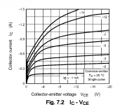
SPICE predicts we have about 1.2V across the drivers, so we just get by by the skin of our teeth. Crisis averted, probably.
Edit: The plot of Vce sat versus Ic paints a more encouraging picture at low collector current.
Edit: The plot of Vce sat versus Ic paints a more encouraging picture at low collector current.
Attachments

Last edited:
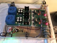
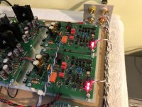
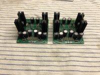
I got the prototype of HPA2 up and running today. It's only one board, and I haven't tried listening to it, so these are just preliminary results.
Performance is really quite exemplary. Bandwidth driven from a 50 Ohm source is 650kHz, limited by the input filter network. Clipping is clean and symmetrical with no rail sticking. Square wave response is picture-perfect. I observed no instability whatsoever. I measured slew rate at exactly 50 V/uS on my scope. This is with no load, just the 2K feedback resistor.
I used the KSC2690/KSA1220 outputs I mentioned earlier in this thread in lieu of the D44/45H11s used in HPA1. The output stage bias current went up to 190mA, or about 3.25W per device, which caused me some concern. But things are running cool with the transistors mounted on a large aluminum plate so I'm going to leave it that way for now.
The amp is a power hog. It draws 260mA on each rail.
The downside of this design is complexity: 29 transistors per channel. I'm amazed it works. As I said earlier, I will start a new thread for this circuit once I have a complete prototype up and running.
Attachments

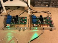
Today, I swapped out the HPA1 boards for the HPA2 boards in my prototype.
I hate to rain on my own party. HPA1 is a very good amplifier, but HPA2 is better. HPA2 retains the virtues of HPA1 -- dead quiet, great detail, strong bass -- and improves on them. Compared to HPA1, HPA2 I think has even better bass. But more importantly, it has a more liquid midrange and is better at "ambience retrieval." It is clean and clear, but relaxed and suave. Soundstage is huge and it feels like it has limitless power.
Granted, depending on your audiophile sensibilities, these differences may be night and day, or they may be nothing at all. I make no claims with respect to my hearing ability or subjective taste -- or whether amplifiers sound different at all.
According to Audio Science Review, I am delusional. Pfffft.
So, this may be the one to build. Except, you can't get the parts for either of them. LOL, sorry. I would love to create a viral smash hit design, but I guess I'm going to have to do it all over with SMD and maybe build my own semiconductor fab to assure a supply of parts.
Attachments
I agree. I think the opa1656 sounds wonderful and can drive 100mA to boot.
I am trying to decide which direction to go on my headphone amplifier projects. Some of my old HPA projects are class A discrete designs going all the way to op-amp plus discrete output stage and even a TPA6120A2.
So I hope you don't mind me asking but what is better (and why) with the complex discrete designs? For example, what if the OPA1656 is put into the attached schematic versus the very nice looking HPA shown in the first post of the thread? I ask since my integrated HPA (such as TPA6120A2 or the parallel op-amp Dougles Self type amplifier) can have great specifications on paper. But I don't necessarily prefer listening to those HPA over extended periods of time.
Any suggestions on reasons why this might be the case?
I am probably going to go ahead and build more discrete designs but I probably will order a few OPA1656 and see what that sounds like in the attached HPA also.
Attachments
Thanks for the question.
As far as I know, there's no good reason to build discrete op amps at all. I'm sure a well-designed HPA with a chip op-amp front end mated to a discrete Class A output stage should work just as well as the circuits I've posted here. I should build one to see for myself.
The only real disadvantage of using chips (or just buying something pre-made from China for a quarter the cost of doing it yourself) is that you don't get that gee-whiz feeling when the project you spent weeks designing and building, with a hundred sixteen parts on each board, blows your mind with how good it sounds.
Edit: WRT your other question, I have no idea why one design sounds better than another. That's not true. I mean, I have some ideas, but I have no way to investigate them. All I know is I have three headphone amplifiers: DCG3, HPA1, and HPA2. When I built DCG3, I thought it was phenomenal, as good as it gets. Then I built HPA1 and I couldn't listen to DCG3 anymore. Now I have HPA2 and it's even better. How good can it possibly get? No clue. I had given up on being an audiophile because I thought it all sounded the same. Now, I'm like "Whoa! WTF?" It's a nuisance, really, but I guess part of the fun.
Last edited:
Do you plan to release gerber files?
Can bc550/560 be replaced with BC 850/860?
Bc850/860 are still in the market.
Can bc550/560 be replaced with BC 850/860?
Bc850/860 are still in the market.
Do you plan to release gerber files?
Can bc550/560 be replaced with BC 850/860?
Bc850/860 are still in the market.
I don't see any reason this circuit wouldn't work well with the SMD equivalents of the through-hole parts. Eventually, all THT transistors are likely to disappear but for the time being everything can be found either at the major suppliers or on eBay. The problem is compounded by the global semiconductor shortage. Other general-purpose transistor types will likely work as well.
Ideally, you would buy enough parts to find matched pairs where appropriate. I used a Peak Atlas DCA75 tester to match transistors.
BC550/560 may be replaced with lower-voltage BC549/559, which might be easier to source.
I used KSA992/KSC1845 because I thought higher voltage parts might be more linear in the VAS output, but that may not be true.
The KSA1220/KSC2690 outputs are out of production and vanishing. D44/45H11 are available and should work as a substitute, maybe with minor compensation tweaks. TTA004B/C are still in production.
LT1761ES5-BYP regulators are listed as active but unavailable until next year, though you can get them on eBay.
The 2N5564 input pair is non-existent. Linear Systems makes a substitute, or you could use LSK389s.
Likewise, the LM329 voltage reference in the Super Regulator is very hard to find right now, though still active.
I sent my HPA1 Kicad design files to a couple of people who asked. I put an archive on Dropbox and can send the link on request. I can do the same for HPA2. Drop me a PM if you are interested.
As I said, I'd be thrilled if more people would duplicate these designs. Thinking it over, these are complicated circuits and still prototypes. I would be sorry if people invested a lot of energy and money in building them and ran into problems. For now, I'm happy to release the designs with the proviso that anyone who tries to build them is signing up for a work-in-progress. This is not at all the most cost-effective way to build a headphone amplifier.
I listened to HPA2 for several hours yesterday and am very, very impressed. I am sad to say it leaves the DCG3 so far behind in the dust (sorry, Salas) that I can't even listen to the DCG3 anymore.
I think HPA1 is close in performance but clearly one thing I learned is the Blameless circuit is finicky about overload recovery. I think it sounds good, but there may be room for improvement. HPA2 has a lot more parts, but so what? It's just a little more soldering. It hasn't so much as hiccuped once and simulates perfectly in SPICE. I can't think of any improvements I want to make to it, so I'll tentatively call it ready for production.
C4 in the compensation network is currently shown as 150nF. I laid out the board for 2.5mm lead spacing on that part. It turns out that the largest I could find that would fit is 100nF, which is what I used. It only makes a small difference in the open-loop response, so no apparent harm done.
A completely new PC board would be needed for SMD parts, or you could maybe build little THT adapter boards for the transistors (though that's a hack, IMHO). Anything is possible, but it takes me many, many hours to lay out a PC board. I've been doing a lot of Kicad work lately and am sick of it. I need to recharge before I start a new project.
I did these projects for the challenge and satisfaction of designing my own discrete circuits. (I hesitate to call them my designs since I'm just copying the works of Mr. Self and Mr. Cordell, for the most part). Chip-based circuits are awesome, but not at all the same thing, so I don't have much to say about them.
If there were more interest in developing HPA2 into a full project, I would consider putting together more documentation and maybe working to make it easier to reproduce. It seems like people are interested in cheaper/simpler designs, and I don't blame them. So for now I've decided not to start new threads, or to embarrass myself by making a big production out of it. I'm satisfied to share my findings and let other people take what they will from it.
I've been thinking about building a small power amp-style chassis for HPA2 with big heatsinks on the sides. With the current board layout, that would make the amplifier almost 4" tall. It would be nice if the boards were a bit narrower so they would fit well on the 80mm heatsinks available from the diyaudio store. The Fischer SK 42/100 is available from Newark, but at 100mm wide, it seems like overkill. A more compact power supply would be nice.
Requiring a separate 12V supply for the relay driver is a nuisance. There is only a small turn-on thump, so maybe the relay isn't needed.
I used a particular grounding scheme for HPA1/2 that seems very effective. That's not shown on the schematic, but I could document it.
That's about everything I can think of with respect to building these things.
Last edited:
Tonight I changed the input capacitors in HPA1 from 56pF to 120pF to address the overload instability I posted about earlier, and repeated my square wave torture test.
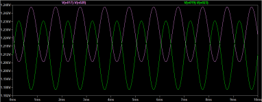
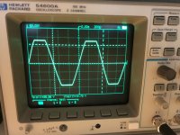
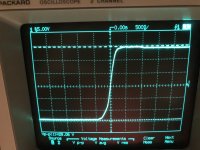
The first photo is sine wave clipping at about 28V pk-pk. As before, it's clean and almost symmetrical.
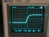
The second photo is a square wave at 27V pk-pk. You can see the waveform is well-behaved with no overshoot.
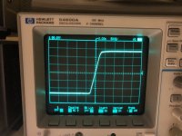
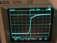
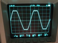
In the next two photos, an odd behavior emerges with increasing drive level.
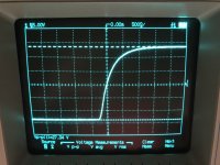
Finally, with hard clipping, it settles down, with just a trace of overshoot. Falling edges look basically the same.
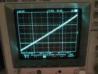
In the last photo, I measured the slew rate at about 145 V/uS. This is driven from a 50 Ohm generator output directly into the amplifier input. It suggests the amplifier is now protected from instability under any input overload conditions.
I measured the small-signal bandwidth at 500 kHz.
I don't know what to make of the intermediate-level blip except to say that as different parts of the amplifier overload, the feedback loop takes about 500nS to figure out what's going on. There was no tendency to burst into outright oscillation, though, as it did before. As I have no plans for listening to full-power square waves, I'm reasonably satisfied with this result.
I'm not sure what I'm going to do with these boards. The BOM parts cost is about $140 for the pair. I also have a pair of prototype stand-alone super regulator boards ($50 each) left over from my DCG3 prototype. If someone is interested in trying HPA1, the boards are in perfect condition and I would be willing to consider reasonable offers.
Otherwise, I will likely build up another breadboard with them, as I'm curious to do a side-by-side comparison with HPA2.
The first photo is sine wave clipping at about 28V pk-pk. As before, it's clean and almost symmetrical.
The second photo is a square wave at 27V pk-pk. You can see the waveform is well-behaved with no overshoot.
In the next two photos, an odd behavior emerges with increasing drive level.
Finally, with hard clipping, it settles down, with just a trace of overshoot. Falling edges look basically the same.
In the last photo, I measured the slew rate at about 145 V/uS. This is driven from a 50 Ohm generator output directly into the amplifier input. It suggests the amplifier is now protected from instability under any input overload conditions.
I measured the small-signal bandwidth at 500 kHz.
I don't know what to make of the intermediate-level blip except to say that as different parts of the amplifier overload, the feedback loop takes about 500nS to figure out what's going on. There was no tendency to burst into outright oscillation, though, as it did before. As I have no plans for listening to full-power square waves, I'm reasonably satisfied with this result.
I'm not sure what I'm going to do with these boards. The BOM parts cost is about $140 for the pair. I also have a pair of prototype stand-alone super regulator boards ($50 each) left over from my DCG3 prototype. If someone is interested in trying HPA1, the boards are in perfect condition and I would be willing to consider reasonable offers.
Otherwise, I will likely build up another breadboard with them, as I'm curious to do a side-by-side comparison with HPA2.
Attachments

After much more work than I expected, I got the HPA1 rebuild working tonight. I still need to finish a few details, but I'm listening to it right now. I wasn't planning on doing this, but I took the DCG3 apart and liberated its power supply for the new build.
My first thought when I started listening to the HPA1 was, "This sounds exactly the same; I'm fooling myself." It's a nice sounding amplifier.
Then I switched back to the HPA2 and had the same impression as my first audition. The HPA2 seems to have a softer overall tonality, with more body in the midrange and more ambience. The HPA2 may have more bass, or it may be that the amount of bass is the same, but the difference in tonal balance makes it seem that way. I hate the word "seems" in audio reviews because it implies uncertainty, but it can also mean, "giving the impression or sensation."
I find this all very interesting. I keep saying I don't have golden ears, and I don't. But it's easy to start thinking like an audiophile, even if you don't want to, as soon as you start listening for differences between equipment. Again, these differences may be very subtle, or illusory. Or, a golden ear type might say the difference is night and day.
At the end of the day, what matters is if you enjoy listening. I decommissioned the DCG3 because, after building the HPA1, I didn't want to listen to it anymore. I'm enjoying the HPA1 right now. They're both good amplifiers, with slightly different characters. But I believe I prefer HPA2.
As always, your mileage may vary.
Attachments
Today, I swapped out the HPA1 boards for the HPA2 boards in my prototype.
I hate to rain on my own party. HPA1 is a very good amplifier, but HPA2 is better. HPA2 retains the virtues of HPA1 -- dead quiet, great detail, strong bass -- and improves on them. Compared to HPA1, HPA2 I think has even better bass. But more importantly, it has a more liquid midrange and is better at "ambience retrieval." It is clean and clear, but relaxed and suave. Soundstage is huge and it feels like it has limitless power.
Granted, depending on your audiophile sensibilities, these differences may be night and day, or they may be nothing at all. I make no claims with respect to my hearing ability or subjective taste -- or whether amplifiers sound different at all.
According to Audio Science Review, I am delusional. Pfffft.
So, this may be the one to build. Except, you can't get the parts for either of them. LOL, sorry. I would love to create a viral smash hit design, but I guess I'm going to have to do it all over with SMD and maybe build my own semiconductor fab to assure a supply of parts.
Oh wow its beautiful... thats gotta be the most elegant/complex vas ive seen on this forum.
Id like replicate/modify this for my own preamp if thats ok with you. Ive been looking for a nice front end to marry with an ic buffer, the same as russ white's ventus, and yours look most apppealing of all. Infact its very similar to russ whites diamente but more advanced.
And if i can cut down the output stage to 1 component ala ic the part count will be just right 😁
Do you think therell be a dangerous amount of power on thump without the relay?
Wonderful circuit regardless. Thank you for posting it!
Oh wow its beautiful... thats gotta be the most elegant/complex vas ive seen on this forum.
Thanks. Credit goes to Bob Cordell, since I cribbed the design almost verbatim from his website/paper. I mentioned this is post #25, but here's the link again: http://www.cordellaudio.com/papers/MOSFET_Power_Amp.pdf
I've uploaded my Kicad project with Gerbers to Dropbox. I will send you a link in a little bit. I'm assuming you know how to use Kicad. There's a couple of symbols that need to be rescued, but I believe the archive is complete. I'll do that by the afternoon.
I don't see any reason why you couldn't bolt an IC output stage on this circuit. If you want to discuss some more, post here or send me a PM.
Do you think therell be a dangerous amount of power on thump without the relay?
I forgot to answer this. I don't know how it would be with other power supplies or output stages, but in my prototype, the turn on/off thump is not very strong with the relay bypassed. The inherent DC offset is pretty low. (I measured 9mV on one channel before installing the servo, didn't bother on the other side.) It takes the servo a few seconds to settle down, but the offset isn't dangerous. The monolithic input pair helps, I assume. The offset might be worse with discrete input pairs, or if your supplies don't come up symmetrically.
I should mention an important detail on the power supplies for HPA2 in case anyone tries to build it. The on-board LDOs are set for 16V output. The front end takes about 30mA from each rail and to keep regulator dissipation low, I run the output stage at 17V, but you could go a little higher. There's no heat spreading on the board for the regulators, so you want to avoid too high a voltage drop across them.
The LT1961ES5-BYP is hard to get now. In theory, the regulators are a good idea, but the circuit should work without them, if you just run the whole thing on the output stage supply. In that case, be mindful of the +-18V absolute maximum rating of the op-amp.
Either way, a regulated main supply is pretty much mandatory for this design. Figure 250mA at idle, and at least 750mA peak current.
After extensive listening tests, I'm going to recommend that people not build HPA1. (That's probably obvious by now.). I really enjoyed listening to HPA1, so much so that I stopped listening to DCG3. But now that I have HPA2, it's the same story over again. HPA1 is a decent amplifier, and I would have been satisfied if I hadn't heard better. But HPA2 delivers much more of the "magic" that "makes you want to keep listening to one album after another." Everything sounds good through HPA2, even at low volumes.
This probably says something about my lack of audiophile skills, but that was the point of these experiments, to see for myself what sonic differences I would hear in different designs instead of talking people's word for it.
Also (this is embarrassing), trying some mods on HPA1, I managed to blow up both channels. I'm not sure how or why. My attempts at a repair made things worse so the HPA1 project is officially over. RIP! 🙂
At Donovas' suggestion, my next iteration might be to put a chip buffer on the output of the HPA2 front end. First I need to take a break.
I do believe hpa2 to be one of the best solution out there if not THE best. Theres really no short cut around high fidelity if you want lower distortion and higher psrr- the architecture will have to get more complex. Ive seen a lot of overly built symmetrical circuits and no doubt they deliver the performance but im betting hpa2 has more of that 'magic' because of its single ended harmonic profile
Last edited by a moderator:
I do believe hpa2 to be one of the best solution out there if not THE best. Theres really no short cut around high fidelity if you want lower distortion and higher psrr- the architecture will have to get more complex. Ive seen a lot of overly built symmetrical circuits and no doubt they deliver the performance but im betting hpa2 has more of that 'magic' because of its single ended harmonic profile
When I was planning a follow-up to HPA1, I looked at fully symmetrical topologies like Cordell's DH220C and Borbely's Servo 100. But something appealed to me about the single-ended front end in Cordell's "MOSFET Amplifier with Error Correction" paper. Compared to the Blameless circuit, though, HPA2 has a complementary VAS. So it's less single-ended than HPA1. The paper points out that this greatly reduces even-order distortion. I have no way to measure it, and SPICE says 0.000000% THD, so I can't comment!
I've read reviews saying that Blameless amps sound a little sterile, so maybe it's a characteristic of the topology. I'm a little embarrassed because I was so keen on HPA1. And, no offense to Salas, but I don't consider the DCG3 to be a serious contender anymore. It's a great project for beginners, though, and has some nice qualities.
The issues with overload recovery in the HPA1 still bother me. No doubt if I were more skilled, and determined to evolve the design, I could get to the bottom of all that, and maybe improve the sound.
I'm listening to Roon in "radio" mode right now. I keep repeating myself, but even not-so-good recordings sound engaging. Don't take my word for it, but to me, at this moment, this thing is sounding good.
Past performance is no guarantee of future returns. Not insured by the FDIC.
Edit: Somewhere in the solid-state forum, there's an argument between Curl and Cordell, which Curl defending the complementary diff topology and Cordell arguing for his circuit. So I was interested to see him go with the Curl-style circuit in the DH-220C.
Well, I felt sorry for HPA1, so I took it apart today and fixed it. You don't even want to know the stupid thing I had done to it. My sincere suggestion is not to attempt mods to equipment, however minor, when it's past bedtime and you didn't sleep enough the night before.
I planned to swap output transistors to the KSA/KSCs, but realized the pinouts are different, so that was a no-go.
It took me hours to disassemble and reassemble the amplifier. When I was done, I turned it on and it sounded like garbage. Then I tried the HPA2 and that sounded like garbage, too. After I had rested, things started sounding much better.
I listened to some Ella Fitzgerald, and then to a nice Oiseau-Lyre recording of sacred music ("Venice Perserv'd", Hogwood, Academy of Ancient Music). TBH, it was quite pleasant on HPA1.
I conclude that there are audible differences between components, but subjective perception is highly variable, and we tend to magnify differences, real or imagined, in our minds. I was convinced last night that HPA2 had spoil'd me, and HPA1 wasn't worth the bother. Now I'm on the fence.
It's impossible to put an objective spin on all of this. If I weren't spending so much money on parts lately, I'd buy something like a JDS Atom to compare. There's not much "How does it sound?" reporting on this forum, so hopefully these impressions are of some interest, for whatever they're worth.
If only there were some instrument we could connect to our equipment that would characterize its performance objectively. Then we could satisfy ourselves that all amplifiers sound the same, and maybe start a forum where it would be expressly forbidden to claim to hear audible differences. At the same time we could all get very indignant about amplifiers that measure poorer than -120dB THD+N.
I don't know what to say. Audio subjectivism is a can of worms. I've read the theories about amplifiers mimicking the distortion spectrum of the ear. Harmonic distortion necessarily generates intermodulation distortion. One of the worst-sounding amplifiers I ever built was the Broskie Aikido line amp. Sounds great on solo guitar. Play anything complex and it turns into a shrieking tsunami of sonic hash. For a couple of years, I had no idea why my stereo sounded so bad.
It's impossible to put an objective spin on all of this.
Yes, Henry, you're clearly right.
There are too much influencing factors and unfortunately THD profile doesn't talk much about sounding.
For example try to change rail capacitors in your amp. With circa 60-80 dBs of feedback depth around output stage your distortion will be neglible but capacitors influence are easily heared. For most of effect pick something best of like Elna SilMic II (RFS) and some ugly ones like Samwha/Elzet.
Next try to change your amp's input to be inverting. Yes, your amp stays the same, only external components changes. Listen to it.
Next put a Murata 78602 1:1:1 common mode choke at the output of your amps.
And more, more, more.
It's long long story.
- Home
- Amplifiers
- Headphone Systems
- New Headphone Amplifier Design