Yes john curl is the MAN. i saw him post a circuit here 9 years ago, the circuit being from 94', that scott wurcer ventually ended up reimagining just last year as a sota discrete opamp.
The downside of this design is complexity: 29 transistors per channel. I'm amazed it works.
In theory, the regulators are a good idea, but the circuit should work without them, if you just run the whole thing on the output stage supply. Either way, a regulated main supply is pretty much mandatory for this design. Figure 250mA at idle, and at least 750mA peak current.
I conclude that there are audible differences between components, but subjective perception is highly variable, and we tend to magnify differences, real or imagined, in our minds. I was convinced last night that HPA2 had spoil'd me, and HPA1 wasn't worth the bother. Now I'm on the fence.
Congratulations for developing and executing the HPA circuits. Much dedicated work.
Although complexity goes up, that's usually necessary to move from a very good to a near perfect lab result.
Output stage power spec and idle current play a significant role when comparing measurements and sound of different circuits on transducers. Especially when trying the lower impedance headphones or loudspeakers.
For deciding better how you like each approach try setting them for same max output power spec at say 32Ω and a comparable idle current.
Its also important to utilize same rails feed architecture down to same types of main regs and front end regs in builds you A-B. Same transformers and electrolytics even. HPA1 and HPA2 use the same main regs, same voltage levels, same front end chip regs, but different output current settings I believe (?).
Thanks for the comment, Salas. And hopefully no hard feelings for the comparison with the DCG3.Congratulations for developing and executing the HPA circuits. Much dedicated work.
I've learned a lot from my experiments this year, but have raised more questions than I've answered. I feel like I've hit on something special with the HPA2, but I have no way to predict what others would find if they were to implement their own builds.
The HPA2 has 15% higher output stage bias current, equivalent to a 0.12V drop in output transistor Vbe. I wasn't expecting that. I should look into it. But I don't have the time or resources to try all the combinations. My family is upset at me for how many days I've spent lately at my workbench.
I'm skeptical of "professional" reviews, but it seems like I need to adopt the same terminology. What I hear going from the Aikido to the DCG3 to the HPA series is a reduction in "grain," which I assume without evidence is due to lowered intermodulation distortion. I imagine that distortion plots would not be that helpful in predicting the final subjective results. I expected HPA1 and HPA2 to have inaudible distortion and to sound exactly the same.
All of this is humbling, and I urge people to take my findings with a large grain of salt. Technically, it's gratifying to get good agreement with theory and simulations on the lab bench, but I beyond that I'm still in the dark.
Edit: Going back over this thread, I notice I keep mentioning the DCG3. When I built that amp, it was such a revelation. The first high-end headphone sound I had ever heard, so I use it as a point of comparison. Truth is, it's a very nice amplifier, too. I would not want to seem to put down anyone's work. Even the Aikido, which doubtless would sound very different with a change of tubes and/or operating points. It's easy to get carried away listening to the latest thing.
Last edited:
Yes john curl is the MAN. i saw him post a circuit here 9 years ago, the circuit being from 94', that scott wurcer ventually ended up reimagining just last year as a sota discrete opamp.
JC is impressive, but I cannot swallow the ByBee nonsense.
What I hear going from the Aikido to the DCG3 to the HPA series is a reduction in "grain," which I assume without evidence is due to lowered intermodulation distortion.
Don't know if its mainly about IMD, should be already low enough, at least between those solid state circuits. Here is what I had measured five years ago for DCG3 IMD SMPTE on live 120 Ohm AKG K612 Pro headphones load. They are not much sensitive cans but they still reach 101 dB SPL at the graph's voltage level. (DCG3 was at 100mA output bias. PSU was DCSTB).
IMHO more revealing to your subjective research efforts would be to bypass the front end reg chips and dial down the output stage bias to 100-150mA in the HPA2 and try hear if the 29 vs 8 transistors upgrade benefits keep as much as before.
Attachments

IMHO more revealing to your subjective research efforts would be to bypass the front end reg chips and dial down the output stage bias to 100-150mA in the HPA2 and try hear if the 29 vs 8 transistors upgrade benefits keep as much as before.
I should use board-level connectors and modular construction to make it easier to swap out different circuits. It's way too hard to take my breadboards apart, and the pads will start lifting if I do it too many times.
The DCG3 is very different, being a two-stage design where the output stage is the VAS. Loop gain is highly load-dependent, of course. I assume the difference in bass authority I hear may be due to the current buffer on the output of the HPAs. It would be worth trying a single-ended output on the HPA2 front end, but that wouldn't tell us much about the DCG3 because it would be an emitter follower instead of a common-source configuration.
The amazing thing about the DCG3 is how well it works without the benefit of all that high faultin' "Blameless" tech. There isn't a single word in Self's book about how the circuit changes sound.
Oh those rapid turnaround boards for prototype testing. Flimsy for rework to say the least, lift pads just upon looking at them. I went through three destroyed such pcbs for examining the Ubib 1.3 shunt PSU until deciding just one configuration parameter before declaring it finished.
I'm using JLCPCB boards and they've tolerated repeated unsoldering/soldering well so far, but there's a limit.
It's an investment every time I solder down a $12 op-amp chip. When I abandoned the first version of the HPA1, I used a heat gun to warm the board until the op-amp fell off. I tried to reuse the chip, but I guess I cooked it because it didn't work after that.
It's an investment every time I solder down a $12 op-amp chip. When I abandoned the first version of the HPA1, I used a heat gun to warm the board until the op-amp fell off. I tried to reuse the chip, but I guess I cooked it because it didn't work after that.
Gel flux helps in rework with a heat gun I have seen through some surface mount cheap gear repairs I did before components went too cooked.
BTW having an emitter follower output buffer can be good security policy in various HP driving for predictable OLG but less so if the primary design goal is for line level mode.
BTW having an emitter follower output buffer can be good security policy in various HP driving for predictable OLG but less so if the primary design goal is for line level mode.
The good thing about no emitter follower is load capacitance increases the phase margin, so no need for an output inductor. The DCG sounded incredible as a line amplifier in my living room system. I will probably put it back together and repurpose it for that, as it has three pairs of input jacks. It's too nice of a chassis to leave sitting on the shelf.
Good for long cables drive. I have tried 1nF capacitor I remember and nothing oscillated. I have a friend who uses six meters RCA to main speakers amp and another six meters in parallel to subwoofers amps.
I'm using JLCPCB boards and they've tolerated repeated unsoldering/soldering well so far, but there's a limit.
It's an investment every time I solder down a $12 op-amp chip. When I abandoned the first version of the HPA1, I used a heat gun to warm the board until the op-amp fell off. I tried to reuse the chip, but I guess I cooked it because it didn't work after that.
For removing expensive SMD op-amps I use ChipQuik low temperature solder and tacky flux. The low temperature solder greatly lowers the temperature and stays liquid much longer. You must use it with the flux. The kit (solder + flux) costs about the same as one $12 op amp but can be used for many chips. I think it is a Bismuth solder. I got it from Circuit Specialists but I think Amazon has it too.
It works well in combination with the relatively low cost Circuit Specialists SMD desoldering tweezers. Use a regular iron to apply the low temperature solder to the chip pins (use the flux first) and then use the desoldering tweezers to lift them off. The desoldering tweezers are worth it if you need to remove/replace a PCM1794 or something like that. They are certainly not the fanciest desoldering tweezers but they are affordable for occasional rework.
It occurs to me that there's no good reason to waste so much power running both sides of the driver stage bias mirrors at the same currents. So, for instance, you could change R37 from 2.2K to 10K, and R36 and R38 to 430 Ohms. This would save you about 12mA of supply current and eliminate the need for R37 to be a power resistor. The values aren't critical and should have no effect on performance.
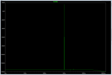
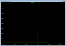
Fooling around in SPICE just now, I compared distortion spectra for HPA1 and HPA2. All plots are with 18V pk-pk output and 32 Ohm load.
The first picture is HPA2.
The second picture is HPA1.
The third picture is HPA1 without the Baker clamp diode.
Can you hear 3rd harmonic at -150dBc? I have no idea what this means in real life.
Attachments

I finally bit the bullet and removed the Baker clamp diodes from the HPA1 just now. (I was traumatized by the other night's fiasco, so had to work up the nerve to take the soldering iron to it again.)
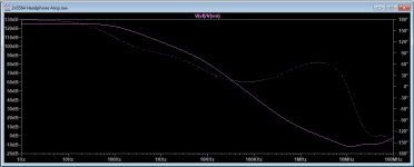
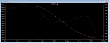
Below are SPICE Bode plots with (first) and without (second) the Baker clamps.
The thing to note is that almost the entire audio spectrum is dominated by the capacitance of the diode. You can see that as the difference between the two loop gain plots. With the diode, we lose almost 20dB of global negative feedback at 1kHz, and the gain of the amplifier is effectively controlled by the diode's nonlinear junction capacitance throughout the midrange.
With conventional Miller compensation, the diode would be in parallel with a typical 100pF capacitor, so its contribution to the overall collector-base capacitance would be a tiny fraction of the total. Not so with two-pole compensation, where the collector-base feedback (without the diode) is much lower at midband.
It's hard to overstate how critical the VAS shunt feedback is to the overall distortion of the amplifier. Miller effect greatly magnifies any nonlinearity in this path. Of course, I'm trusting the sound of my amplifier to industrial-grade C0G ceramic capacitors, so who knows? In theory, these are very good parts, ceramic notwithstanding.
I'm now finding it extremely hard to hear a difference between the two amplifiers. The tonality sounds identical to me. That is to say, I get the same initial sense that it's just a little too smooth, but after a short time I start to hear "into" the music better and it all sounds very natural.
I still want to say the HPA2 has an edge in ambience and soundstage, but the overall difference in sound is much smaller now and could be an artifact of my imagination. I'm running both amps with the pots wide open and using Roon to control the volume to keep the levels matched. In theory their gains are identical, though the HPA2 sounds maybe a tiny bit louder to me, who knows? The HPA1 breadboard has a pair of 40 year-old Bourns 10K plastic pots on the input, whereas the HPA2 has a precision 20K metal-film stereo stepped attenuator. If you believe those things matter, it could be significant.
In principle, the VAS may be vulnerable to damage due to overload, and we're back to rail sticking and maybe oscillation on clipping. In this regard, the Cordell is the clear winner. I'll see about making some new measurements of that tomorrow.
I guess the point is, that yes, when you make the transfer function of your amplifier an exponential curve, even tired old ears can hear it.
Attachments
With the diode, we lose almost 20dB of global negative feedback at 1kHz, and the gain of the amplifier is effectively controlled by the diode's nonlinear junction capacitance throughout the midrange.
To clarify, I should have said "the open loop gain is effectively controlled..." The overall closed-loop gain will still be determined by the global feedback network. But the diode nonlinearity, while greatly reduced by feedback, will still be there, and will create a slew of higher-order distortions, which probably aren't modeled very well by SPICE.
Edit: On the other hand, all these distortions are still going to be a very low levels, thanks to the huge amount of NFB in the circuit. It's all a mystery to me. I really like the Cordell circuit, intellectually, and feel a powerful emotional tug to prefer it in listening tests regardless of what my rational brain tells me.
Last edited:
I've decided not to try to test clipping on the HPA1 without a VAS current limiter. SPICE says the peak base current in the KA992 will be 95mA, whereas the data sheet lists the absolute maximum as 10mA. Maximum rated collector current is 50mA. I don't feel like blowing transistors.
This leaves me at somewhat of a dead end. I could go back to the original design with the VAS current limiter and its nasty clipping recovery. I could add a current limiting resistor, either to the VAS base, or in the collector of the beta-enhancement transistor, with a slight increase in distortion and an unknown effect on stability. Or I could add more parts and try to implement a Cordell-style clamp. All of this would require another run of boards, and I'm not in the mood for building HPA1v3.
I've been listening to both amplifiers again this morning, wearing the plating off my RCA connectors. The HPA1 is sounding very nice. Listener fatigue is setting in and it's all starting to sound the same to me.
Seems like I've achieved my objectives. I've proven I can put together a high-performance discrete amplifier of semi-original design. I've built a couple of different circuits and identified and corrected a sonic issue that's plausibly related to a valid technical cause. I've shown that increasing complexity (from DCG3) yields an apparent improvement in subjective performance (to my ears). And I've reached a level where subjective differences are so subtle that I have a hard time distinguishing them.
I would like to quote this gem of a quote from Audio Science Review:
I'm trying to think of where to go next, or maybe I will just take a break and humor my wife by working on some household projects.
This leaves me at somewhat of a dead end. I could go back to the original design with the VAS current limiter and its nasty clipping recovery. I could add a current limiting resistor, either to the VAS base, or in the collector of the beta-enhancement transistor, with a slight increase in distortion and an unknown effect on stability. Or I could add more parts and try to implement a Cordell-style clamp. All of this would require another run of boards, and I'm not in the mood for building HPA1v3.
I've been listening to both amplifiers again this morning, wearing the plating off my RCA connectors. The HPA1 is sounding very nice. Listener fatigue is setting in and it's all starting to sound the same to me.
Seems like I've achieved my objectives. I've proven I can put together a high-performance discrete amplifier of semi-original design. I've built a couple of different circuits and identified and corrected a sonic issue that's plausibly related to a valid technical cause. I've shown that increasing complexity (from DCG3) yields an apparent improvement in subjective performance (to my ears). And I've reached a level where subjective differences are so subtle that I have a hard time distinguishing them.
I would like to quote this gem of a quote from Audio Science Review:
The 789 and A90 will sound the same, they are both transparent well measuring amps, and no amount of deaf, biased, deluded audiophiles can change that. Placebo is real though, if you convince yourself things are going to change, you'll be happier after spending the cash.
I'm trying to think of where to go next, or maybe I will just take a break and humor my wife by working on some household projects.
Attachments

I think I've either bored you all to tears, or gone so far off the deep end into subjectivity that everyone is rolling their eyes at me.
After more listening tests, it stills seems to me that the sound improved after removing the Baker clamps from HPA1, but I don't trust my own ears. I'm also confused by the fact that the clamping in HPA2 doesn't seem to cause a problem.
The difference in the HPA2 clamp scheme is the diodes are referenced to fixed potential, not placed from the input to output of the VAS. The cascode collectors are a high-impedance node, so the diode capacitance should have some effect, but they aren't bootstrapped by the VAS gain and don't affect the compensation curve noticeably in SPICE.
Does anyone have experience with the subjective effect of using Baker clamps across the VAS? The clamps work so well on the test bench, it's a shame not to have them in the circuit.
- Home
- Amplifiers
- Headphone Systems
- New Headphone Amplifier Design