Hi Zoran ,
Kali receives data on raising edge and sends on falling edge.
I think that should be:
All outputs at rising edge of the cycles in any case, word length and sampling rates.
...
For instance:
Point where L/R latch changes state from 0 to 1, that is rising edge.
At the same point, MCK , and SCK should go from 0 to 1.
That should be changed in firmare (if it is not like that)
AND
one cycle of SCK (BCK) from that point should be 0.
Every full cycle of BCK AFTER LR latch changing the state should be 0.
Is there any Flip-Flops at the I2S bus lines for recklocking, after the FIFO?
...
IF they are present in the form of ONE flip-flop per I2S line, that is causing outputs from flip-flop at the falling edge... And 1/2 of the clock delay or shift.
...
Only 2 flip-flop one after another, PER line, deliver at the output same rising edge like on the input. Also avoiding "meta-stabile state"...
...
IF they are present in the form of ONE flip-flop per I2S line, that is causing outputs from flip-flop at the falling edge... And 1/2 of the clock delay or shift.
...
Only 2 flip-flop one after another, PER line, deliver at the output same rising edge like on the input. Also avoiding "meta-stabile state"...
Master or slave
Sorry, my understanding is not good even tho I have built plenty of DACS in the past.
I read that "Kali will not work if your DAC is a master. DAC has to be slave." however I do not have a good understanding if the DAC is master or slave. In my case I am looking at using the Kali between an RPi3 and Subbu DAC with I2S input. Subbu uses the es9023 DAC chip and has a 50MHz oscillator feeding the MCK pin. Does this mean the DAC is running master? If so do I need to modify so the MCK pin is fed from the MCK output on the Kali?
Thanks in advance.
Your DAC is running slave. No need to feed your DAC with an external MCK.
Your DAC is running slave. No need to feed your DAC with an external MCK.
Thanks for that, good to know.
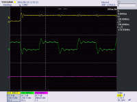
This is the latest reading on 16 bit. It works fine ..
This is done with lots of wires around..lots of ringing because of it, a better capture is coming that reflects better .
This is done with lots of wires around..lots of ringing because of it, a better capture is coming that reflects better .
Attachments

Last edited:
Correct.
We actually have flipflops on fpga but apparently they don't solve this meta stability problem.
We actually have flipflops on fpga but apparently they don't solve this meta stability problem.
Is there any Flip-Flops at the I2S bus lines for recklocking, after the FIFO?
...
IF they are present in the form of ONE flip-flop per I2S line, that is causing outputs from flip-flop at the falling edge... And 1/2 of the clock delay or shift.
...
Only 2 flip-flop one after another, PER line, deliver at the output same rising edge like on the input. Also avoiding "meta-stable state"...
This is the latest reading on 16 bit. It works fine ..
This is done with lots of wires around..lots of ringing because of it, a better capture is coming that reflects better .
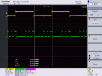
@ first picture is Latch L/R yellow, and System clock (BCK) magenta
BCK has to be inverted. (IF latch follows L and R datas...)
...
When L/R goes from 0 to 1 rising edge, BCK goes from 1 to 0 fallen edge...
Please correct software.
And MCK should be also going from 0 to 1, same as the L/R and BCK (after inverting)
Hi, Yes please try to invert the BCK green line.
Wheh LR goes from 0 to 1 rising edge, BCK goes opposite from 1 to 0 falling edge...
Should be like this:
And MCK output AT The same place should go from 0 to 1 also rising edge.
...
One BIT clock BCK after LR change state. Should be no data bits. Most significant bit starts from 1 period of BCK AFTER LR change.
...
All word formats - all sampling rates
Attachments
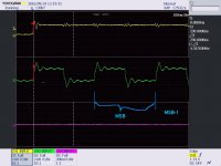
the MSB has a fixed position, whereas the position of the LSB depends on the word length.
The transmitter always sends the MSB of the next word one clock period after the WS (LRCLK) changes.
Serial data sent by the transmitter may be synchronized with either the trailing (HIGH-to-LOW) or the leading (LOW-to-HIGH) edge of the clock signal. However, the serial data must be latched into the receiver on the leading edge of the serial clock signal, and so there are some restrictions when transmitting data that is synchronized with the leading edge
Last edited:
Hi Zoran ,
First lets look at MSB, you are correct that MSB is the second bit...but before the MSB its the LSB or the padding (not exactly sure) of the previous sck..so basically "there should be no data" is wrong.
Second you say that when LRCK is rising , BCK should also rise.. that is incorrect. LRCK rising --bck is falling , lrck falling --bck falling
Hi Zoran
What I said for 3-4 times and illustrate with pic - please...
🙁
Attachments
Last edited:
cdsgames
It is true. I think there is no 32bit DATA real word length?
The LR latch is usually 32 bit long per channel 16 to 24 bit. Other bits are empty.
You can measure it in mode of "32bit" option. I measure other interfaces and almost all had 32 bit long LR And data was changed 16 to 24 bit.
...
I2S will work even with that like in the picture You post.
BUT it is from the importance and it would be better that Master clock dictate the BCK and be in sync with BCK. Because probably BCK and LR are from one of the Master clock oscillators, regarding Fs base 🙂 and running the "First in first out"
...
Could You Please post some MCK and BCK signal?
...
(I am not writing without the reason - preparing to order 2 pieces to test... 🙂)
Last edited:
One note on meta stability of Kali and generally of flip flops
The flip flop that we chose has a Tsu (0.4 to 0.7) and Th (hold time) of -0.3 to 0 so time constant , worst case scenario , is 1ns
""The external interrupt signal is async, so will eventually violate tsu or th. The 'there was an interrupt this cycle' signal gets read in two places. If the program counter thinks there was an interrupt, and the interrupt controller thinks there wasn't, crash!
While there is no cure for metastability, it can be controlled. Any flip flop will be settling with a small time constant, which in a well designed system is small fraction of the clock period. For a particular violation, let's say there is 100% of the output becoming metastable. After 1 time constant, there is a 1/e chance of it still being metastable, 36%. After 10 time constants, it's only 36/million. That may not sound too much, but with a 10Mhz clock, that's 360 failing events per second, far too many. After 20 time constants, it's about 1/billion.
(copied from internet) ""
Basically with the fastest 48Mhz clock we should have about 20.8 time constants (20.8ns clock period) so 1/1 000 000 000 BCLK will be switched to the next MCLK
Bclk/Data is not a problem since we are talking about same time constant FF but clock period changes to 85ns
Only 2 flip-flop one after another, PER line, deliver at the output same rising edge like on the input. Also avoiding "meta-stabile state"...
It is not about speed and time delay.
Simple every flip flop delay 1/2 of the master clock, signal at output.
after all signals recklocked that master clock comes like inverted in respect to the other signals.
...
Could You please post MCK and BCK outputs?
Simple every flip flop delay 1/2 of the master clock, signal at output.
after all signals recklocked that master clock comes like inverted in respect to the other signals.
...
Could You please post MCK and BCK outputs?
New Kali boards are being shipped today. 44/48Mhz up to 384.
Tomorrow we will be up to date.
16 bit bug solved.
Tomorrow we will be up to date.
16 bit bug solved.
I pulled the trigger as well for one Kali board. I bought it from Volumio website, which seemed to be the only shop with euro prices and VATs.
I'm planning to use the Kali reclocker with Raspberry Pi 2 (Moode Audio) and my DDDAC-board. Hopefully this will solve my problems of having only mono audio with red-book (16bit/44.1kHz) material. And ofcourse I'm expecting a better sound in general too. My current I2S-reclocker is a Hifiberry DAC+pro.
I'm planning to use the Kali reclocker with Raspberry Pi 2 (Moode Audio) and my DDDAC-board. Hopefully this will solve my problems of having only mono audio with red-book (16bit/44.1kHz) material. And ofcourse I'm expecting a better sound in general too. My current I2S-reclocker is a Hifiberry DAC+pro.
Last edited:
- Home
- Vendor's Bazaar
- New FIFO buffer for RPI/SBCs