@cdsgames
This is completely preliminary, just initial setup/experimenting.
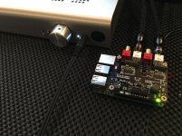
I plugged in the piano, booted with your max2play image... there is crossover high/low output on both dac's (set to 60Hz sub output)
Hooked into my headphone amp, is the output supposed to be so low? In the pic thats the headphone amp set to high gain & volume maxed, and it is still quiet... maybe this is correct for your AMP board? Seems low for the sub output via: RCA
This is completely preliminary, just initial setup/experimenting.
I plugged in the piano, booted with your max2play image... there is crossover high/low output on both dac's (set to 60Hz sub output)
Hooked into my headphone amp, is the output supposed to be so low? In the pic thats the headphone amp set to high gain & volume maxed, and it is still quiet... maybe this is correct for your AMP board? Seems low for the sub output via: RCA
Attachments
Of course you are right, looking at the ES9018's datasheet confirms that.
So do you have a ready-made overlay in mind that might cater to these demands?
Is the Pope catholic?
simple-bclk-64fs-overlay.dts
as good as the Piano's near perfect power/noise situation for the PCM5142 chip, without the Kali it's fighting the pi i2s (non master mode) with it's PLL.
Don't get me started...... I've made the "pig in lipstick" comments. I'll leave the negativity there. My views on the TI PCM5 series, (whether PLL is slaved to extremely jittered Pi BCLK or not), aren't exactly a secret. 😉
Kali has its output lines on its (Kali's) GPIO header, on the exact same pins.
This way you can mount a HAT DAC on top of Kali, like you would on top of the RPi.
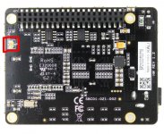
MCLK output is via U.FL socket on the bottom of the board.
Thanks, Dimdim 🙂
could You please if You have some picture, point where is the MCK output?
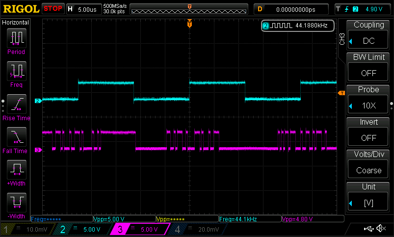
For the record, these are two captures of a 16bit I2S stream, playing a 440Hz sine wave on the left channel only.
This one is the RPi's output:

And this one is Kali's output:

I'm surprised that this I2S stream produced actual music..
IN I2S specs is that MSB bit (most significant bit) is ONE BCK (Sys CLK) after the L/R latch changed...
So I think the input have some bits NOT one bit after L/R change but right in L/R changing state? So in input bus MSB is not present because DAC wil not read it since it expect MSB and other to come one BCK clock after L/R change.
...
Other one, output i2s bus, should be not producing music... 🙁
DAC SUB output...should go to amplified SUB (I use LFE input)
@cdsgames
This is completely preliminary, just initial setup/experimenting.
I plugged in the piano, booted with your max2play image... there is crossover high/low output on both dac's (set to 60Hz sub output)
Hooked into my headphone amp, is the output supposed to be so low? In the pic thats the headphone amp set to high gain & volume maxed, and it is still quiet... maybe this is correct for your AMP board? Seems low for the sub output via: RCA
No change (still 3ps) , but our main Oscilloscope is back to dealer for some small problem. We will get it back Monday
For 352/384 we will blink some LEDs
For 352/384 we will blink some LEDs
@cdsgames
On the 352800/384000 Kali... do these new clocks change the 3ps spec? Any other changes? Is this the Kali 2?
Did you find a place to stuff 2 more LED's re: 352K/384K 😛
dimdim, the image doesn't expand for me either (after refreshing)...
It seems that my Rigol managed to generate a semi-standard PNG file that does not render on some systems.
Here it is again, fixed I believe:
@Dimdim, your 2nd scope output is blank...
Browser sensitive for me. Firefox nay, Chrome yay!
IN I2S specs is that MSB bit (most significant bit) is ONE BCK (Sys CLK) after the L/R latch changed...
So I think the input have some bits NOT one bit after L/R change but right in L/R changing state? So in input bus MSB is not present because DAC wil not read it since it expect MSB and other to come one BCK clock after L/R change.
...
Other one, output i2s bus, should be not producing music... 🙁
Could this explain the traces HF glare I experienced that seemed a bit out of place compared with the rest of the presentation?
@clivem, @Dimdim
Did you guys see this ?... as good as the Piano's near perfect power/noise situation for the PCM5142 chip, without the Kali it's fighting the pi i2s (non master mode) with it's PLL.
@Dimdim you did a writeup on this... the pi raw i2s
The RPi's I2S is definitely bad, but I believe it's worth doing a comparison with/without Kali. It's good to have a baseline..
I agree that a better test is Kali vs. master mode DACs.
could You please if You have some picture, point where is the MCK output?
Attachments
thanks 🙂
So noow it is clear.
Kali do not have input MCK? But only output MCK selected probably from one og the oscilators present, with a respect to the time base 44.1KHz or 48KHz n x sampling rates.
...
The input I2S bus - 3 lines, is from bottom pins at the conn
Output i2S bus - 4 line, 3 + MCK
...
One thing should be checked:
what is going on with the MCK and SCK lines are they from the rising edge of the clock or falling edge. other words if they are like it should be or inverted?
...
for the reference please take a look on the I2S standards.
Browser sensitive for me. Firefox nay, Chrome yay!
Could this explain the traces HF glare I experienced that seemed a bit out of place compared with the rest of the presentation?
I cant tell for that, but one thing is for sure MSB is right after 1 SYS clk cycle from channel change status, and if it is not on tat position, DAC will not read...
...
thanks 🙂
So noow it is clear.
Kali do not have input MCK? But only output MCK selected probably from one og the oscilators present, with a respect to the time base 44.1KHz or 48KHz n x sampling rates.
...
The input I2S bus - 3 lines, is from bottom pins at the conn
Output i2S bus - 4 line, 3 + MCK
...
One thing should be checked:
what is going on with the MCK and SCK lines are they from the rising edge of the clock or falling edge. other words if they are like it should be or inverted?
...
for the reference please take a look on the I2S standards.
AND
I cant tell for that, but one thing is for sure MSB is right after 1 SYS clk cycle from channel change status, and if it is not on tat position, DAC will not read...
Zoran,
Honestly, I am not sure any of the drivers for the R-Pi output a MCK. None of the R-Pi DAC HATS I have here or that I'm familiar with input an MCK from the Pi. Even the HiFiBerry DAC+ Pro which runs in Master mode uses the BCK as the master it sends to the Pi.
Also, none of the other reclockers with which I am familiar, Ian's Async and Acko's synchronous setups input a MCK.
Also while the output glitches are clear in the scope pix, the Kali works and the improvement is clear in using the device. I DO expect clearing up the glitches will only improve the sound.
<SNIP>
Could this explain the traces HF glare I experienced that seemed a bit out of place compared with the rest of the presentation?
Simon, in my setup I noticed a slight HF emphasis, tho not enough to call it a glare . I'm hopeful the waveform corrections will improve this, anxiously awaiting an updated Kali. In the meantime, I am letting the device run 24/7 to ensure the unit has every chance to fully break-in just in case that impacts what I hear... and listening a few minutes last night did suggest it made an impact, along with trying some alternative capacitors on the output of the 5v reg feeding the Kali.
My status on testing the unit is that I'm getting things setup to use the Kali on devices other than the Mamboberry in my system:
1. I'm adding a power feed from the R-Pi raw supply to the 5v regulator I mounted on the Kali so I can use the Kali on the Pi feeding one of my Soekris DAC setups (should be interesting as the Soekris DAC already does reclocking, but this is a Gen1 unit that does that entirely in the FPGA, not an ideal setup).
2. I'm adding a small 3.3v regulator fed from the expansion header 5v on the IQAudio DAC I have here so I can run it with the current Kali that does not pass-through the Pi's 3.3v.
3. I'm looking at whether the Dexa 5v regulator I'm using on the Kali will work ok with the Kali->Piano combo. It tops out at 600mA and is not heatsinked, I may need to replace it with a stouter unit (I have a 2A Belleson 5v reg I can use there).
I'm doing these upgrades in coordination with power supply configuration changes to support a couple of optical networking FMC's I just installed between the Pi and the rest of my small music-only network so I can run them from linear supplies instead of the stock SMPSs. BTW, having these in my setup and having an optical instead of a wired link between my source server and other networking gear and the Pi produced another nice SQ bump, nicely complementing that of the Kali.
Once I get these done, I'll start another round of listening tests and report back here.
Greg in Mississippi
Honestly, I am not sure any of the drivers for the R-Pi output a MCK. None of the R-Pi DAC HATS I have here or that I'm familiar with input an MCK from the Pi.
Guys, if you want a SBC board that outputs MCLK, buy something other than the RPi. Odroid C2 is probably the closest in price, if you want something that does. Pin 4, on the 7 pin I2S header, ISTR.)
Hi Zoran ,
Kali receives data on raising edge and sends on falling edge.
Kali receives data on raising edge and sends on falling edge.
thanks 🙂
So noow it is clear.
Kali do not have input MCK? But only output MCK selected probably from one og the oscilators present, with a respect to the time base 44.1KHz or 48KHz n x sampling rates.
...
The input I2S bus - 3 lines, is from bottom pins at the conn
Output i2S bus - 4 line, 3 + MCK
...
One thing should be checked:
what is going on with the MCK and SCK lines are they from the rising edge of the clock or falling edge. other words if they are like it should be or inverted?
...
for the reference please take a look on the I2S standards.
just as a general comment....
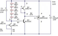
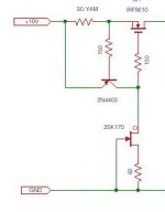
if anyone wants the ''best sounding reg'' for 5v, i'd go with salas shunt regs, especially for 5v and above. I have tried many regs (superreg,ldo's,sigma22,tl431,lm317(the lm317 sounds surprisingly nice for some reason...),etc.) and that one is without any doubt the all around champion. There are many versions that will give different flavors and each part substitution gives a different sound. Right now i'm using the attached topology wich i find the best. i'm not using these parts though.....the first part swap i'd make is change the ccs and shunt mosfet for irfp9240 (or irf240 for a negative version). As for the rest of the parts, it's a question of taste, according to me.
i also have a very nice 3.3v version using 2sj313 as shunt , but it is not a widely available part....i'm still trying to find a good sounding one that can be ordered about anywhere.
so just my impressions, but i've spent many hours comparing and listening 🙂
edit:
just wanted to add: there is a ''digital'' salas reg i have yet to try, so this is not a final testi have done, but it's a good (very) start 🙂
Attachments
Last edited:
Zoran,
Honestly, I am not sure any of the drivers for the R-Pi output a MCK. None of the R-Pi DAC HATS I have here or that I'm familiar with input an MCK from the Pi. Even the HiFiBerry DAC+ Pro which runs in Master mode uses the BCK as the master it sends to the Pi.
Also, none of the other reclockers with which I am familiar, Ian's Async and Acko's synchronous setups input a MCK.
Hi Greg, right,
that is why I asked, IF there is INPUT MCK to the FIFO then could be option of sort of sync. mode. But the FIFO is targeting Ras Pi, which as i catch does not have MCK output.
According to I2s specs:
VLow < 0.4V
VHigh > 2.4V both levels able to drive one standard TTL input (IIL =–1.6mA and IIH = 0.04mA)
Input Levels:
VILow = 0.8V
VIHigh = 2.0V
The I2s Bit-clock (BCK) taken directly fron the RPi GPIO meets the above specifications (output level I2s specs).
Obviously, the ultra HF noise shown on the osciloscope traces is significantly higher in the case of a RPi , but within the safe zone.
A proper termination of I2s lines is needed at the receiver end (i.e. the DAC) and this might further improve the performance of the RPi2 I2S lines
Last edited:
- Home
- Vendor's Bazaar
- New FIFO buffer for RPI/SBCs