salas said:
... will make Babo happy!
Thanks, Salas
Sure, I'm happy learning that Type A on post #166 is working as confirmed by your sim on post #174 🙂
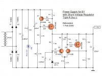
Then, this Type C would also work . . . if the gate of Q5 is connected correctly to the collector of Q3.
Type B as modified by Leapcat . . . ? In principle, yeah . . .
Which one I should try to build first . . . ?
Cheers,
>>🙂<<
Attachments

salas said:
Is this a faster version?
Hi Salas, I don't know? I use sims to get close. I am curious of its response but I need to build it to find out.
Babowana said:
Thanks, Salas
Sure, I'm happy learning that Type A on post #166 is working as confirmed by your sim on post #174 🙂
Then, this Type C would also work . . . if the gate of Q5 is connected correctly to the collector of Q3.
Type B as modified by Leapcat . . . ? In principle, yeah . . .
Which one I should try to build first . . . ?
Cheers,
>>🙂<<
You are welcome!
I would build the one with Q5 IRFP9240. P Mosfets I like better there, and BC550C has stronger hfe than 560C all the times I measure some.
and when you are done, measure the voltages across R8 and R10.
Calculate the currents through these two resistors.
Are they exactly in the ratio 1:2?
add a temporary 20k pot across R9.
adjust until Ir8=Ir10/2.
Measure the combined resistance of R9//pot.
Now replace R8 and R9 with resistors of this value.
And while you are at it add 4k7 to R7.
Is this to feed one B1 or a stereo pair?
If a stereo pair then R1 may need to be reduced a bit, somewhere between 6r3 and 9r1.
An alternative is to leaves long tails on the back of the PCB ready to add parallel resistors to trim each (R1, R8, R9) of the values, or breadboard and find out why it is not working as expected.
AndrewT said:and when you are done, measure the voltages across R8 and R10.
Calculate the currents through these two resistors.
Are they exactly in the ratio 1:2?
add a temporary 20k pot across R9.
adjust until Ir8=Ir10/2.
Measure the combined resistance of R9//pot.
Now replace R8 and R9 with resistors of this value.
And while you are at it add 4k7 to R7.
...
An alternative is to leaves long tails on the back of the PCB ready to add parallel resistors to trim each (R1, R8, R9) of the values, or breadboard and find out why it is not working as expected.
I
 why these are necessary . . .
 The citcuit on post #184 will work 🙂
Cheers,
Babowana said:
I
The citcuit on post #184 will work 🙂
Cheers,
Babowana, What AndrewT said is a good idea. A little to much Vgs on Q5 and the power rail goes to ground. Then things get hot! If I were building this circuit I would make the differential part first and drive the power rail with a current limited power supply. Then adjust for values.
Babowana said:Matching . . . ? Is it necessary . . . ?
I don't care of the output "DC" offset voltage.
>>🙂<<
Will secure symmetry and performance. Best is to match hfe (with a simple DVM that has hfe feature and socket), and even better put them in face to face contact, with a touch of thermal grease between, and a tie wrap around so to hold them together. That will go towards better thermal tracking for the dif pair. In case you find practical difficulties, you can always follow ''Plan B'', aka what juma made.
I'm confused . . . 
As far as I understand, Q3 and Q4 would not share the Ic current exactly equally on operational condition. At the moment of power on, the base voltage of Q4 would be started from zero and be increased to Vb close to the zener voltage, then Q4 would be turned on and Q5 would be also turned on, controlling Vb to stay there . . .
Am I wrong?
Okay, let me try to build it with mismatching Q3 and Q4 and with no thermal coupling between them. I'd like to see what would happen . . .
>>🙂<<
Attachments
The Long Tail Pair (LTP) is measuring the difference between two voltages and sending the error signal to control the output voltage.
As a differential amplifier it works best if designed to operate as a differential amplifier. That means matched transistors, operating at the same Vce0, operating at the same Ic, operating at the same temperature and operating with constant current in the tail.
When the LTP detects a pulse or glitch it sends a correction to try to shunt the pulse/glitch to ground.
If one can arrange the circuit to make the AC or noise or pulse sensitivity higher, then all the better.
Is there room to substitute a tl431 and two resistors in lieu of the Zener?
Make it like that as well Babo, looks nice. I was just talking about best performance. As Andrew explained better.
Thanks, Andrew and Salas, for your kind advice 🙂
Well noted and I fully agree with you that the matching TRs give much much better performance.
Oh . . . by the way, I have reduced R8 and R9 from 10K to 4.7K, to see the minimum collector voltage of Q3 and Q4 at about 10V on the condition that all the tail current flow through either Q3 only or Q4 only.
Cheers,
>>🙂<<
Attachments
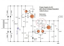
stick the LED in series with R5. If it lights then you know that Q1 is passing.
Change R7 to 4k7 or 5k0.
Change R7 to 4k7 or 5k0.
AndrewT said:stick the LED in series with R5. If it lights then you know that Q1 is passing.
Change R7 to 4k7 or 5k0.
Are you trying to tease me? 🙁
Or, trying to scorn me? 😡
neither, I'm serious.
R4 & R5 do the same job as R14. Why add an extra resistor?
And if the LED lights it confirms more than just DC voltage on the supply rail.
A green one would indicate "go"
Similarly, a green LED in series with ZD1 would indicate that you have output voltage as well. To accommodate this reduce the Zener voltage to ~7V.
GRollins said:I've seen fairly decent arguments for use of shunt regulators in circuits that effectively draw DC, but they're based on waste (or not, as the case may be) of power, not sonics.
Grey
Here's an article from a guy that recommends a shunt regulator after an LM317 to lower noise. If I recall correctly, in this contextt it's used to improve the phase noise performance (i.e. jitter) of oscillator circuits. That's his main field of interest. His point is you can use his circuit to shunt noise to ground for a 20-40 dB improvement over a standalone LM317. I notice his LM317 circuit does not shown a cap to gnd on the adjustment pin, which may makes his improvements less dramatic. Nonetheless, it's a different take on the approach from "it sounds better".
http://www.wenzel.com/documents/finesse.html
Not to be overlooked is his initial comment about using a healthy series inductor followed by a cap to ground for lower current circuits. This combination can clean up a LOT of garbage in my informal tests.
I have a bunch of 1H 1.5" dia. toroids that may work well for that sort of thing, say in place of the 1 ohm resistor on the B1 when using a wall wart supply.

- Status
- Not open for further replies.
- Home
- Amplifiers
- Pass Labs
- New-building of my B1 buffer