Babowana said:
Doctor says that two more chemo treatments are waiting for me . . . Now, I take a walk through a small mountain behind my apartment at least one hour everyday . . .
Awesome.
Just walking my dog a 1/2 kilometer is as much walking as I am doing lately.
To Mr You's health


My wife does not walk any dog, but me 
This morning, she did not know how to handle camera. When I gave her my camera and asked to take one shot for me, she spent long time until she could finally press the shutter botton. I didn't know what she was thinking about looking into the viewfinder. My face was complaining her taking so long time while I was trying to make smile . . .
I'm loosing hairs (mostly black) and getting hairs (mostly grey) steady-state at this length for the time being so that I don't need to go to barbershop . . .
🙂
Attachments

Very best of luck with the chemo. Its rough. For what its worth, you don't look too bad - not the classic "look" of someone who is receiving chemo. I hope you keep well, take those treatments your doc has for you and make a good recovery. The fact that they are talking about just 2 more is a good sign I reckon.
Very best of luck to you.
BTW, on topic: If my current B1 etch don't work out, I'm going to draw out yours! Will power it with a teddyreg gyrator based PS all going well!
Very best of luck to you.
BTW, on topic: If my current B1 etch don't work out, I'm going to draw out yours! Will power it with a teddyreg gyrator based PS all going well!
Babowana said:My wife does not walk any dog, but me .
I'm loosing hairs (mostly black) and getting hairs (mostly grey) steady-state at this length for the time being so that I don't need to go to barbershop . . .
🙂
Let It Grow ....Have'nt been to a barber since chemo four years ago.... Get Hip ..Tie it back and trim the ends! Best to you and GOOD LUCK.. I know you'll make it!!🙂
Babowana said:steady-state
A perm and a blond hair dye job would look great on JH.
Babowana said:I'm loosing hairs (mostly black) and getting hairs (mostly grey) steady-state at this length for the time being so that I don't need to go to barbershop . . .
After all this time you grace us with a picture.
😎
Hi All,
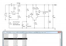
By chance, I have downloaded the free LT Spice and, as a first trial, I have tried it with the schematic in post#206, Babo Shunt Type A.
Since LT Spice doesn't have 9.1V zener, I have put 10V zener instead. And, I have replaced ZTX TRs to BC546/556.
Hah . . . 🙂 ! It seems working. With Vin of 30Vdc, Vout appears as 20.5125V. It's interesting. I have tried DC analysis only . . . I need to learn other LT Spice functions too! How learn . . . is a big question tho . . .
>🙂<
Attachments
Hi Babo,
what are the voltages across the two collector loads of the LTP.
I think you will need to reduce these collector load resistors slightly to balance the LTP.
Breadboard it and measure the real voltages to find Vgs of the output FET.
what are the voltages across the two collector loads of the LTP.
I think you will need to reduce these collector load resistors slightly to balance the LTP.
Breadboard it and measure the real voltages to find Vgs of the output FET.
AndrewT said:
Breadboard it and measure the real voltages to find Vgs of the output FET.
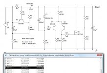
I have built Type A and used it about one month in 24-hour-on status. Attached is the measured voltages for your info.
JimT said:
Jim, many thanks for the info!
>🙂<
Attachments
It looks like the voltage across the other collector load is ~5.2V and not 3.3V to match the other half of the LTP.Babowana said:Attached is the measured voltages for your info.
Reduce the 4k75 collector resistors to about 3k7 (not a standard value) to get equal currents in the two halves of the LTP.
Thanks, Andrew.
By the way, why the "equal currents" are so important in this kind of operation? I always want to know the reason before I should do something.
>🙂<
By the way, why the "equal currents" are so important in this kind of operation? I always want to know the reason before I should do something.
>🙂<
Hi,
your circuit works by comparing almost identical signals and outputing a factor times the difference.
The comparison is done by a differential amplifier and this is the LTP part.
An LTP works best as a differential amplifier if both halves operate with equal amplifying abilities, i.e. matched devices, matched voltages, matched currents.
This way a true difference signal is the output, subject to the distortion and noise limits of the amplifying devices.
Try adding a pair of parallel resistors to the existing pair of 4k75, start with 18k or 20k and measure the voltages.
The next value, 16k, may be too low but worth trying anyway.
An alternative is to add a trimming pot in parallel to the third (tail) resistor and use that to adjust until voltages match. But that requires you to remove the existing tail resistor and replace it with a higher value. Probably 7k5 // 20kpot. The disadvantage of this method is that you can't define the tail current in advance due to the unknown Vgs of the FET on the output.
AndrewT said:
...
This way a true difference signal is the output, subject to the distortion and noise limits of the amplifying devices.
...
Hi Andrew,
I will decline any comment about the distortion.
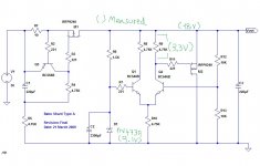
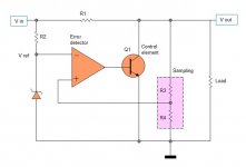
I don't think there is any "true" different voltages between non-inverting and inverting inputs. Pls refer to the attached simplyfied shunt regulator (from a text book). There should be a "certain" voltage difference between non-inverting and inverting difference so that there should be a "certain" output voltage to drive the control element (bipolar or mosfet or else).
I think that we need to see other things regarding the noise . . .
>🙂<
Attachments
Hmm . . . the chemo is getting tougher . . . just finished the 9th . . . It seems to be the last one . . .
Yeah . . . I need to make myself happy doing what I want to do. I'm thinking to build one more B1, using another shunt regulator, say Babo Shunt Type E.
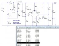
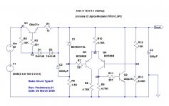
I have a 10VA EI transformer of 2X18VAC secondaries. I believe that this size is big enough for B1. Meanwhile, I have found few leftovers of TIP31C bipolar TRs, which I have bought times ago when I have built my first BOZ. So, I want to use these for a new shunt regulator.
The attached scematic is the LTspice model only for a simple simulation. When I actually build it, however, I think I need to change some parts, for example, R1, R5, D1, D2, Z1 and R13 . . . most probably . . .
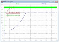
In the LTspice model, I have given two input voltages--22Vdc and ac sine voltage having 0.5V amplitude (1V peak to peak) at 100Hz.
>🙂<
Yeah . . . I need to make myself happy doing what I want to do. I'm thinking to build one more B1, using another shunt regulator, say Babo Shunt Type E.
I have a 10VA EI transformer of 2X18VAC secondaries. I believe that this size is big enough for B1. Meanwhile, I have found few leftovers of TIP31C bipolar TRs, which I have bought times ago when I have built my first BOZ. So, I want to use these for a new shunt regulator.
The attached scematic is the LTspice model only for a simple simulation. When I actually build it, however, I think I need to change some parts, for example, R1, R5, D1, D2, Z1 and R13 . . . most probably . . .
In the LTspice model, I have given two input voltages--22Vdc and ac sine voltage having 0.5V amplitude (1V peak to peak) at 100Hz.
>🙂<
Attachments
I hope so, this ninth one because of that the last one, dared already there's no need.
We need you!
Best wishes:
Gyuri
We need you!
Best wishes:
Gyuri

- Status
- Not open for further replies.
- Home
- Amplifiers
- Pass Labs
- New-building of my B1 buffer